Hello everyone.
At the request of Timoore,
I'll make
you share the achievement of an airplane for FlightGear.
Above all, let me
clarify that what follows is a way of doing things, but in no case the
way of doing things. I believe that the current 3D, even if it becomes
more and more powerful
is not yet enough to be able to adhere strictly to a plan. This
may take days or we will have real-time 3D engine in ray-tracing, which
will use more facets to define the forms but rather mathematical
formulas like POV, for example.
To be honest, I do not even know me use the most advanced features of Blender.
I must go next to a lot of things great. But I admit, when there is
less than a year,
on December 16, 2006, I started H4 Hercules, I knew that Blender name. I had
never used. All this to say
that despite an interface that may repel the outset, it is actually
quite simple to handle. And it is quite
easy to do something with it.
Note:
All images are available in real size, just click on it ;)
To begin with, the choice of aircraft. In this case, after
a short discussion with the
concerned, our choice is brought to the Breguet
Br-761 "Deux ponts"
("two bridges"). One of the rare "Deux ponts" to have
stolen. And French which is not to displease me.
We will see then how easily transform Br-763 "Provence".
Well, thus entering the heart of the
matter. First, find a plan 3 views the greatest possible to have a
maximum of definition in the modeler.
Here's what I found on the site of Richard
Ferrière (a gold mine for plans aircraft):
Then we must cut three views and cropper (that is the fact to minimize
the size of the image
around the plane to leave no empty on the sides).
Personally I use Gimp, but you do as you see fit.
Here is the result. I have added a frame
around to fully understand.
A front view:
A view from side:
And a view from above:
Now that we have the views, we will seek the dimensions of the beast. A
small tour on the net and as always we find our
happiness here:
|
Wingspan:
|
41.66
|
m
|
Length:
|
28.70
|
m
|
|
Height :
|
9.53
|
m
|
Surface-bearing:
|
178.70
|
m²
|
|
Passengers:
|
130
|
|
|
|
|
|
Empty
weight:
|
22050
|
kg
|
Total
Weight:
|
38000
|
kg
|
Three values only concerns us right now. The wingspan, length and height.
Well, what to do with these three images.
First, in the case of Aircraft
data file of FlightGear we must create a
folder to accommodate this new aircraft. We will therefore
create Br-761 and then again in this case another
folder Models. Here we see the other later.
We therefore:
.......FlightGear/data/Aircraft/Br-761/Models
We
will immediately put our three images previously made.
Now we are launching Blender
(or any other modeler at your convenience). I share
the principle that Blender is known I am not here
to make a course on the use of a modeler.
Some use functions
background images. Personally I prefer to use plans that I accommodate depending on my
needs. We will
create 3 shots each on a plan of orthonormal.
The plan which lies along the X axis is the length, along the Y axis
scale and of course along the Z axis we have the height. And we put a veneer images.
Of course we dimensionnons plans functions of the dimensions found
earlier.
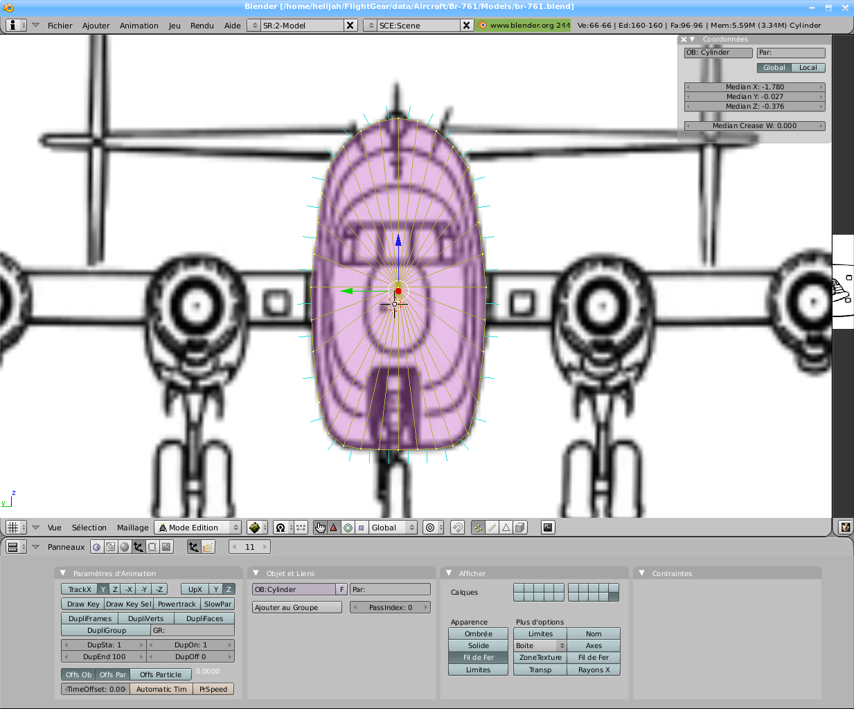
And as you can see the bottom of the
image, 3 plans are placed in the layer number 10. Now turn
in the layer 1 while leaving the layer 10 to the screen and turn to
face (Shift 3 of the keypad).
This gives us this: File Blender available here
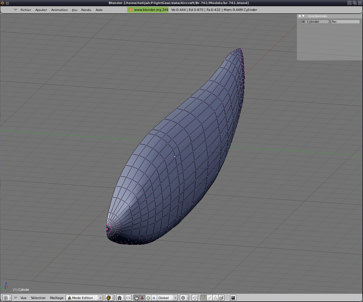
We begin by creating a cylinder (32 sides seems a good
compromise between finesse modelling and simplification of the 3D
model) in the center of the universe Blender.
Having taken care to focus the plans we have a cylinder at the centre
of 3 plans.
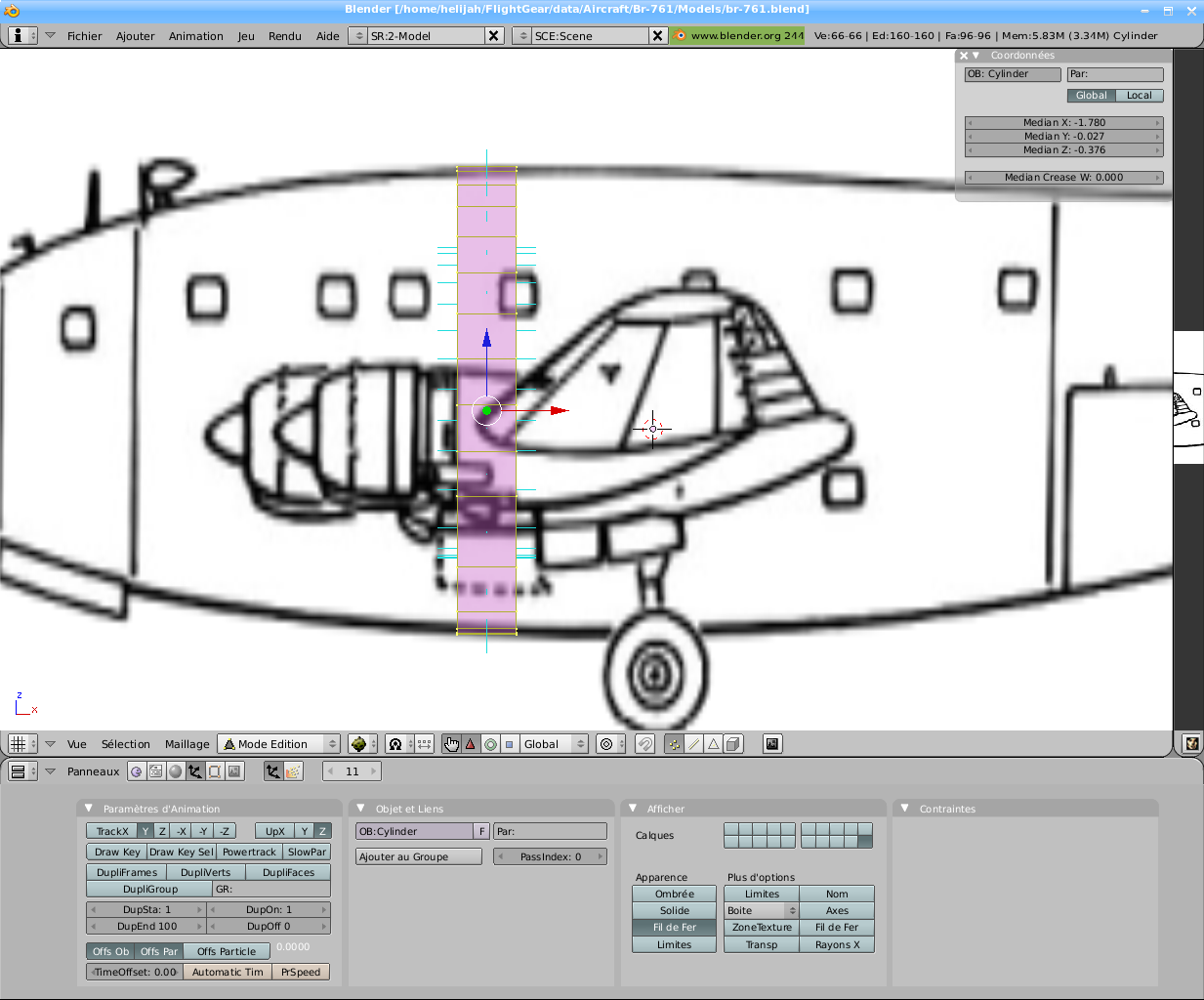
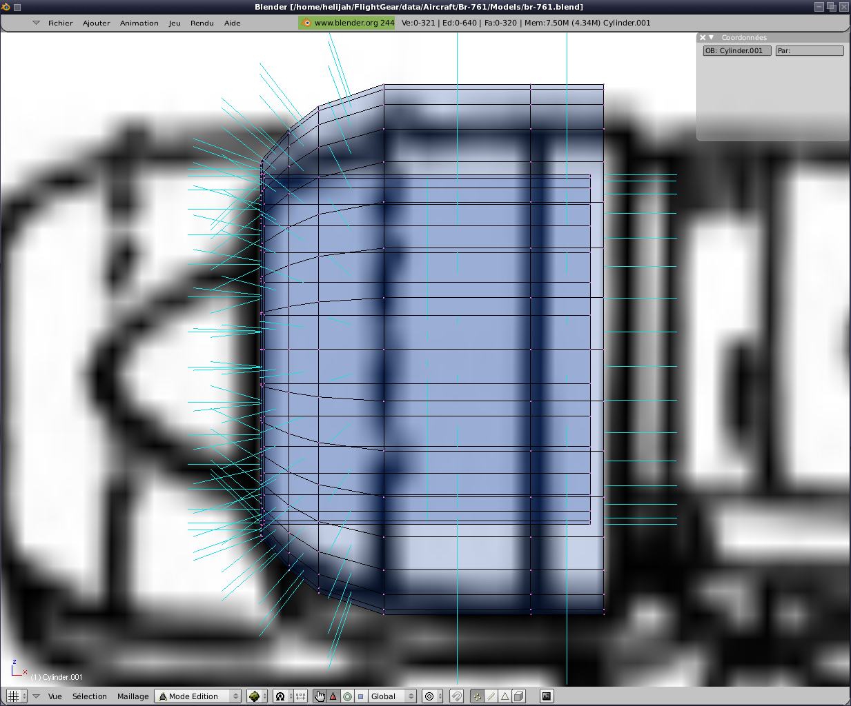
Also in front view,
we retouchons the cylinder to come marry the external form the biggest
in the fuselage. We can play on the width, height and the change of
position a few points.
At this point it
is important to do everything symmetrically. Later we will eliminate one side.
Skip to side (shift
1) to change the size (X) of the cylinder and place where the fuselage
is greatest.
Well, we will re-select all
the points and select only the points of view in the left side:
With the function extrusion (key 'E') and change of size (key "S") we
will follow the profile forward, then backward.
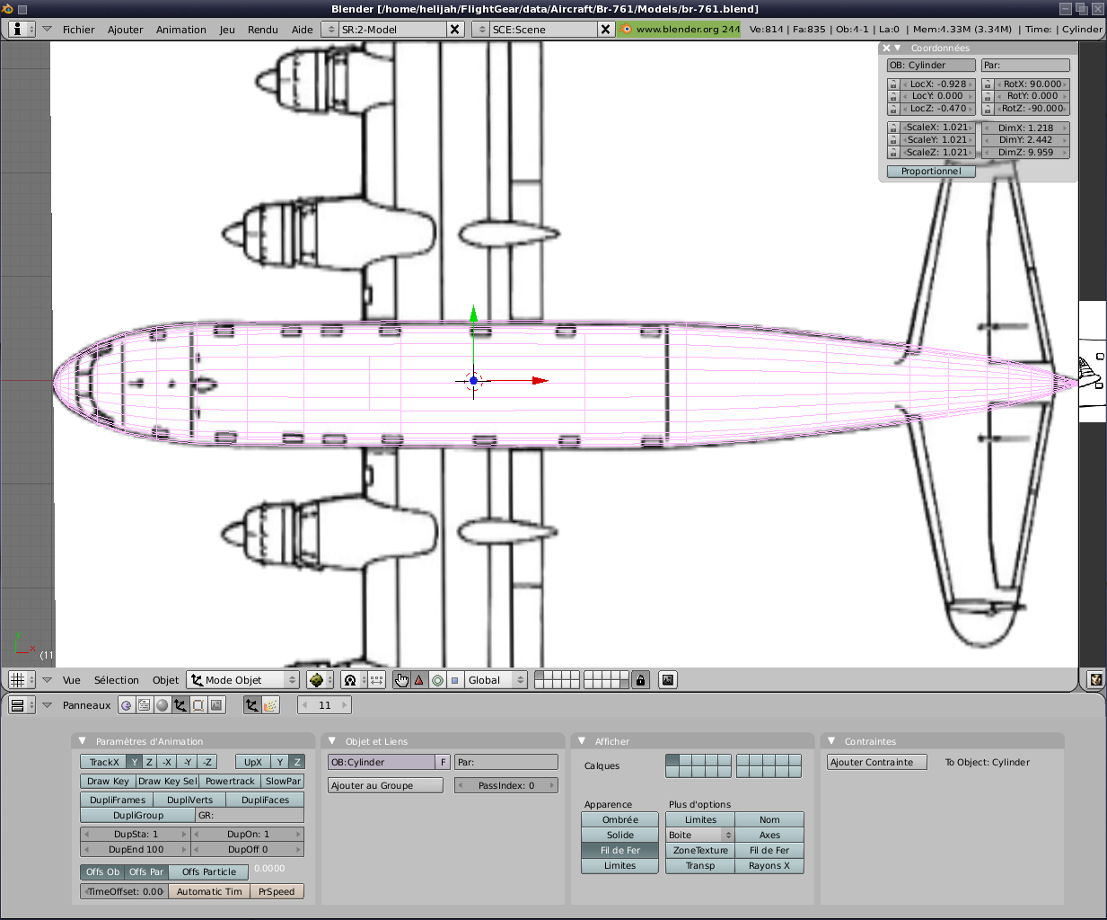
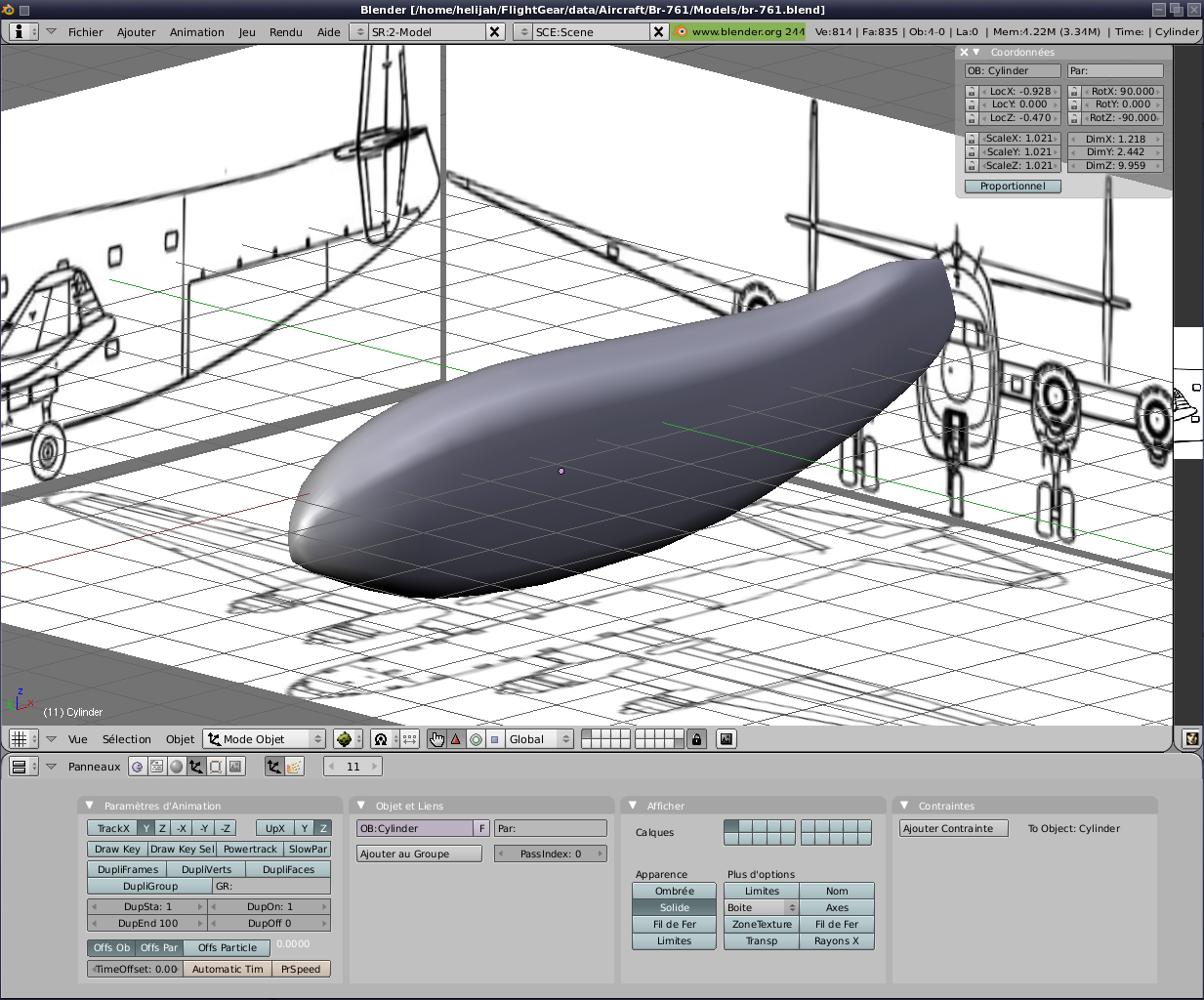
Of course it gives us a profile, but the width
is not necessarily respected. So we'll move to above (7 of key
keypad) and then with the 'B' select slice one by one and through key
'S'->' Y 'only adjust the width following the plan's most
faithfully as possible.
Did you
pleasure and you look at the result in full ;)
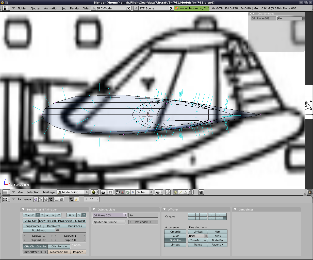
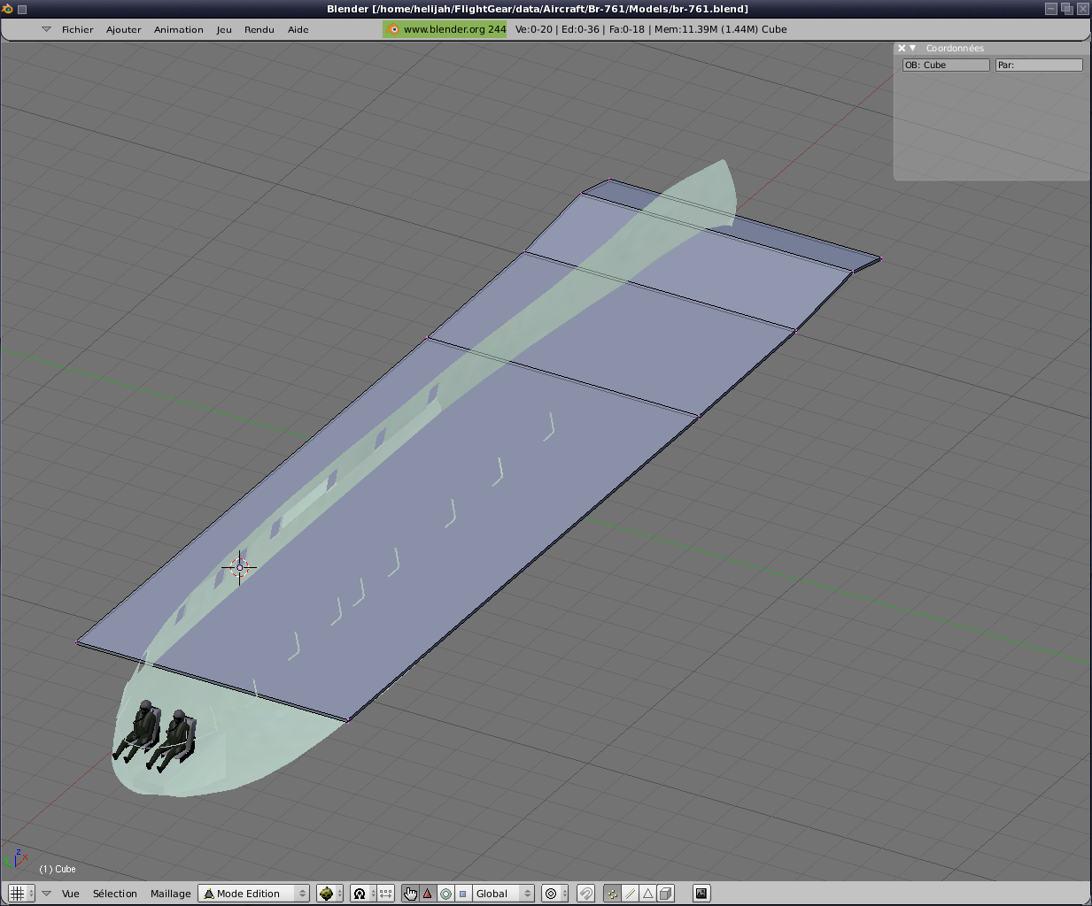
It is time to
remove one side for now work in symmetry and go for it and start a wing.
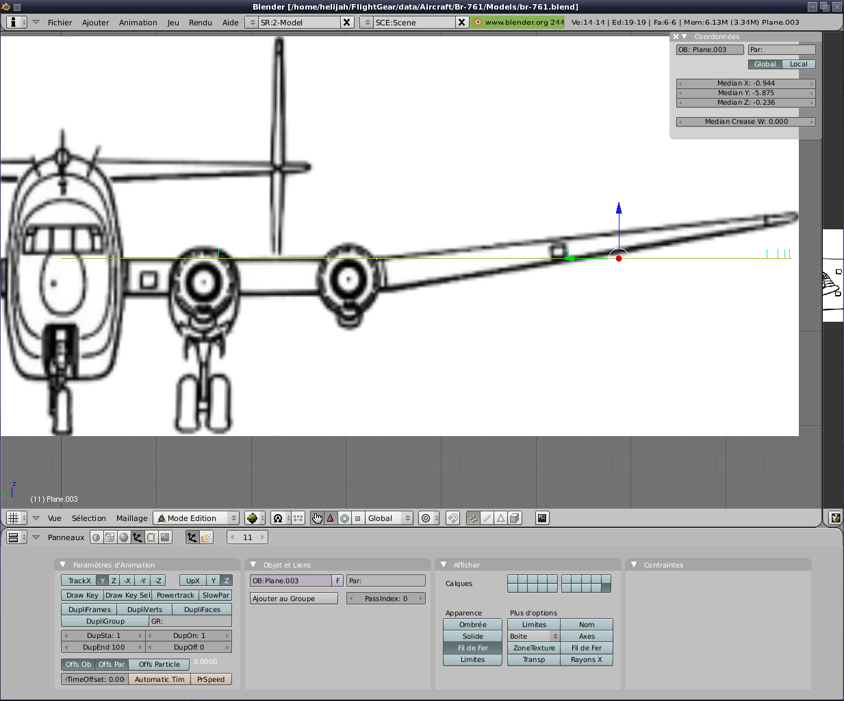
Many methods exist for that. Personally I start with a plan.
Method simple,
effective and relatively light polygons. So we
start with a plan in place following the profile of the wing following
the same principle as above for the fuselage.
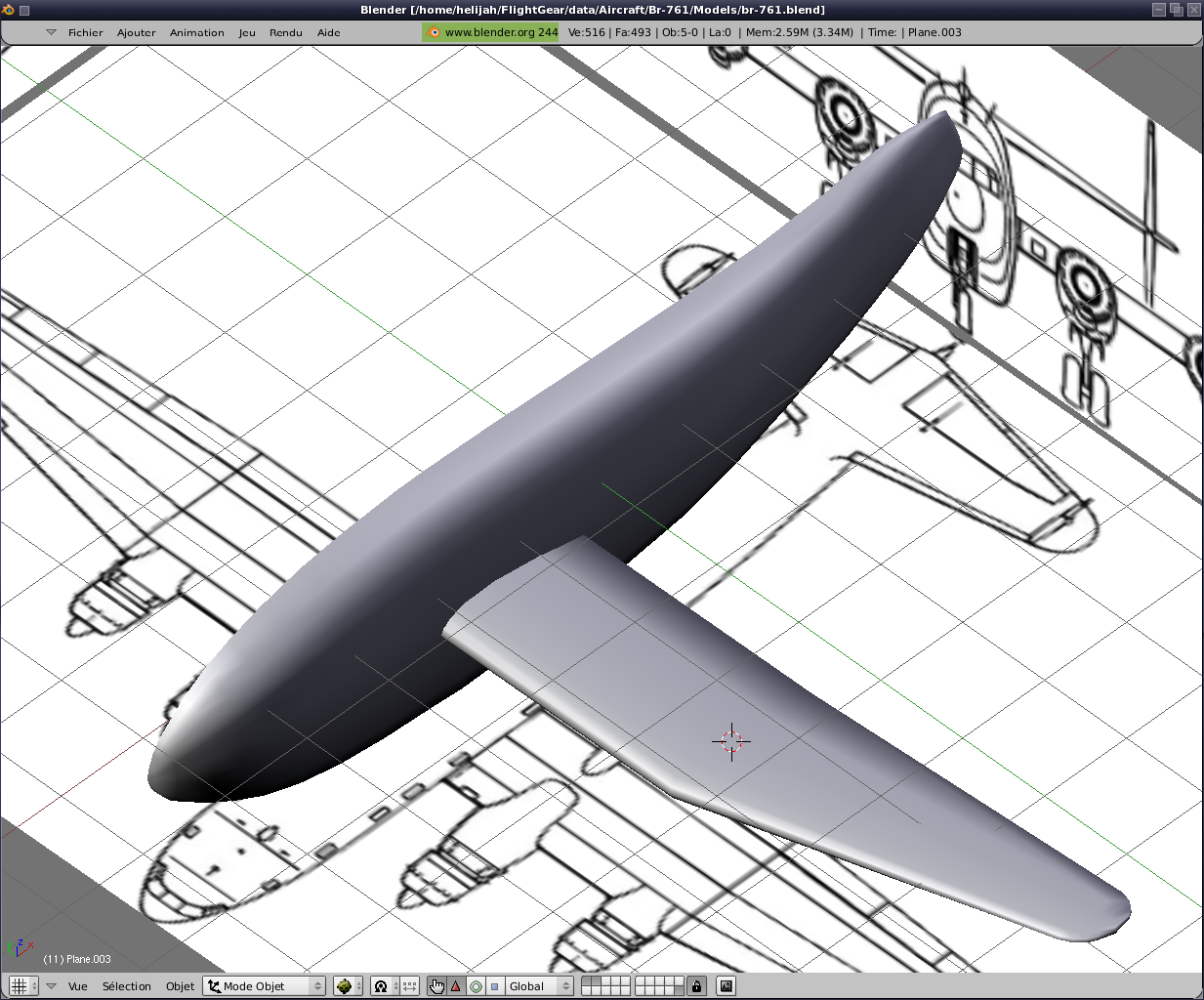
Passage in front view and positioning the plane on the top of the wing.
By extrusion we give a
thickness to our wing. Now give him his profile. In order to side, we select all vertical edges and then we divide (an
odd number for a line of points perfectly centered on the height, here
I chose subdivisions 7).
We then select only the points located in the
centre and in front of the wing, then using the proportional edition we
create the leading edge of the wing. We recalculate the
width and we go to the rear. There is much
simpler but less realistic. Indeed,
we are going to reduce its vertical size to 0.
Note: A thick 0 does
not exist in reality. But we
are not going to "chipoté" :)
After a few adjustments, including on the tip
of the wing, we can return to face. Start with slightly reduce
the thickness of the tip of the wing, then a rotation we have just
marry the plan.
Next strictly the same
method, we can immediately achieve the elevator and drifts.
Now add the wheels of history have enough land the aircraft.
To do this, I cheated slightly.
Having made wheels, which I find
rather successful for the UH-60,
we will recover them.
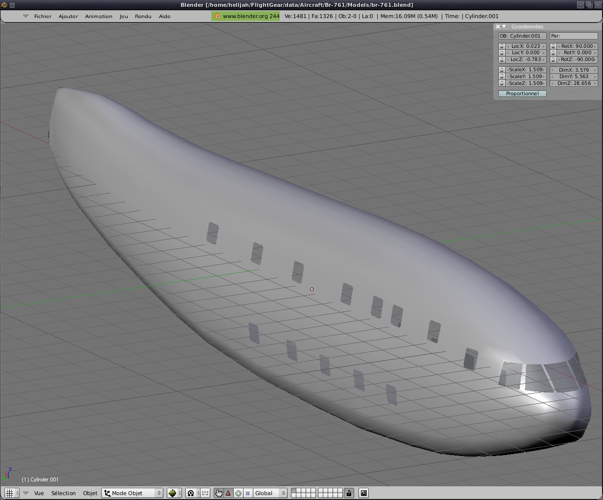
We are, therefore,
if we remake the symmetries with an aircraft without an engine but
already beginning to have an identity ;)
Before continuing, a
small precision. All the pieces created must
have a name. Not only
the parts which will be mobile, but also others. Thus, the fuselage will be named "fuselage, the
wings will be" wing "etc
... I would do a summary at the end.
Well, an aircraft
without an engine hum .... ... is a glider. Out of our Breguet is a four
engines. It is time for us
to provide a little power.
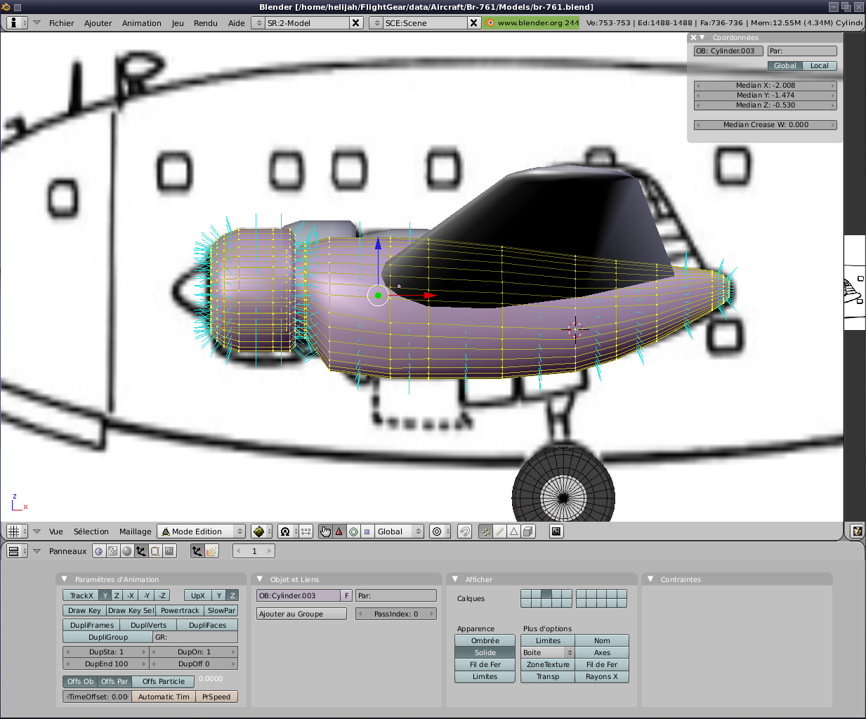
Well, I spent the comments.
Also on the same principle. The fuselage. Cylinder, extrusion,
skilful touches ...
Did it is time to see the
head he has a FG. To do so, we will use an existing FDM, we will simplify life.
I
personally used one of my personal Noratlas. After some minor (change of paths to find the files, change file names
etc. ..) The result is already not bad ;)

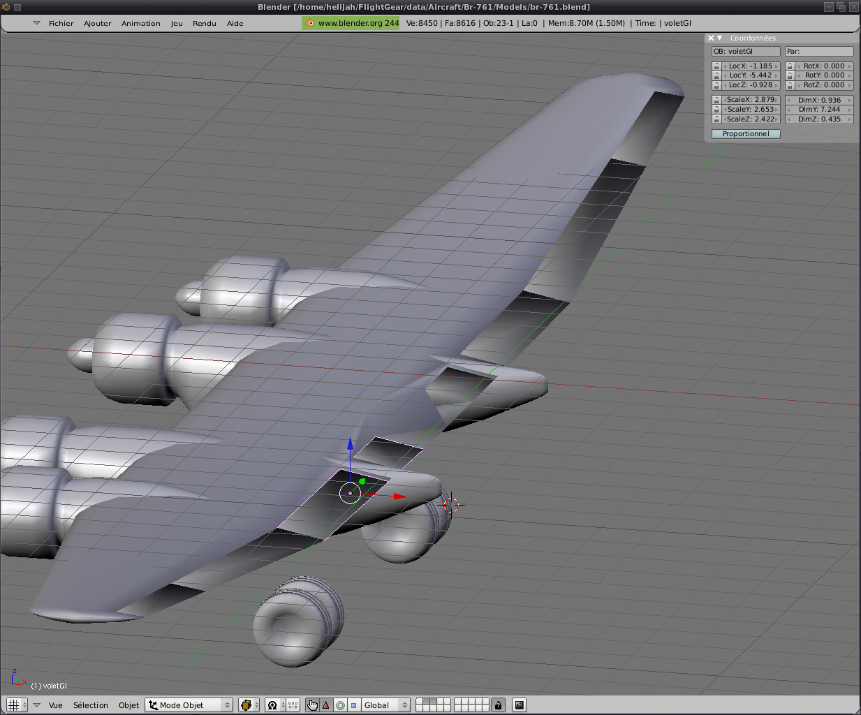
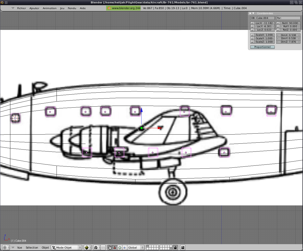
So, in general, when I come to this stage, I begin to worry
animations. Also going to go to the various parties mobile base. That is, ailerons, flaps, rudders and depth. All this will be done on one side of the
camera and then postponed by symmetry on the other side.
|

|

|

|
| image 1 |
image 2 |
image 3 |
|

|

|
|
| image 4 |
image 5 |
|
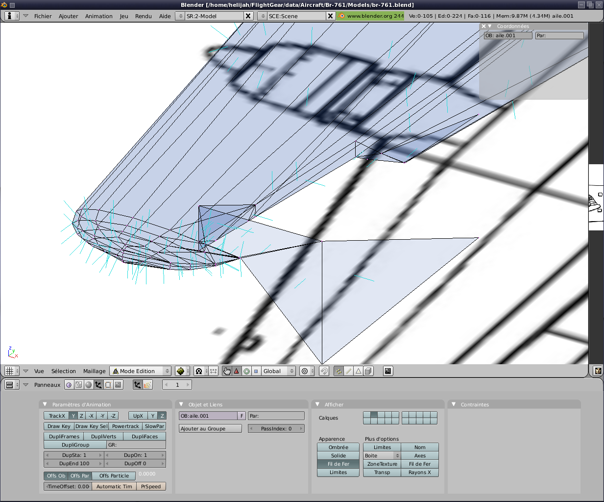
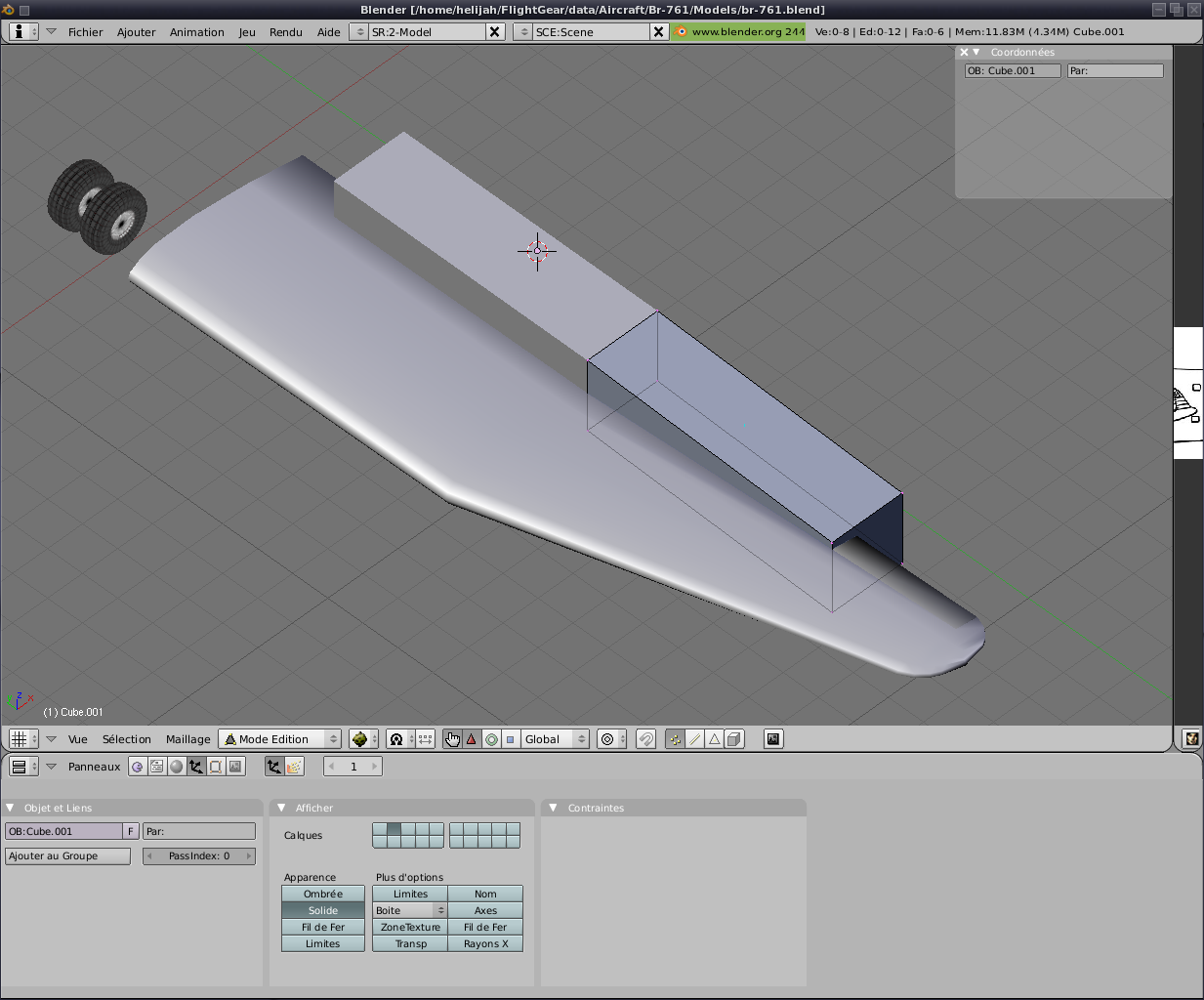
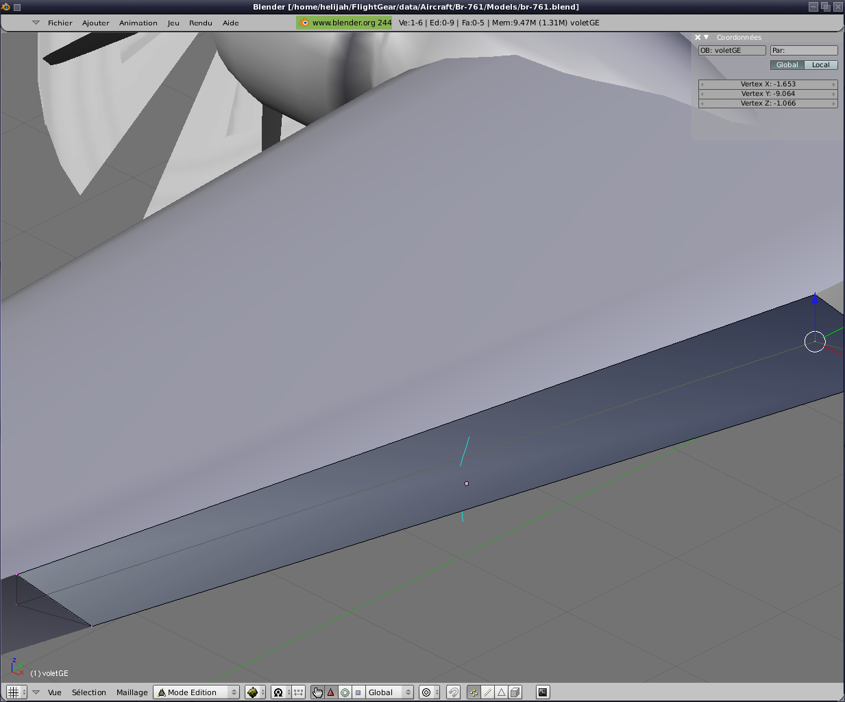
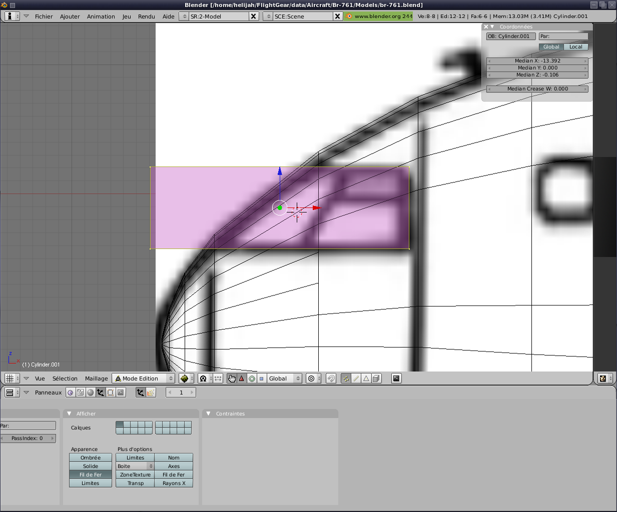
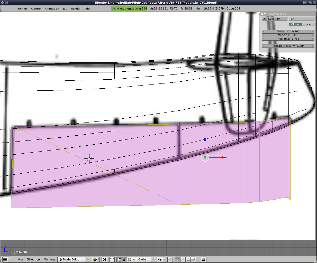
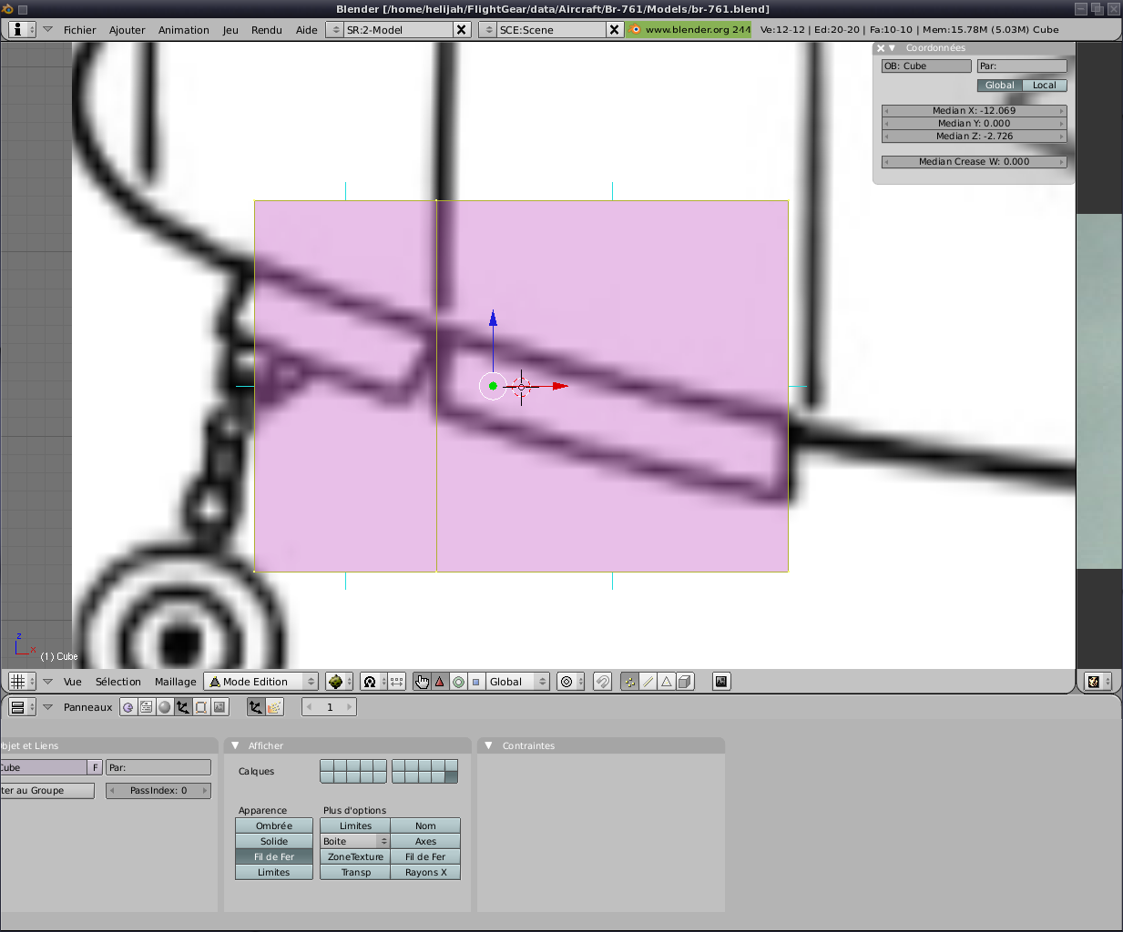
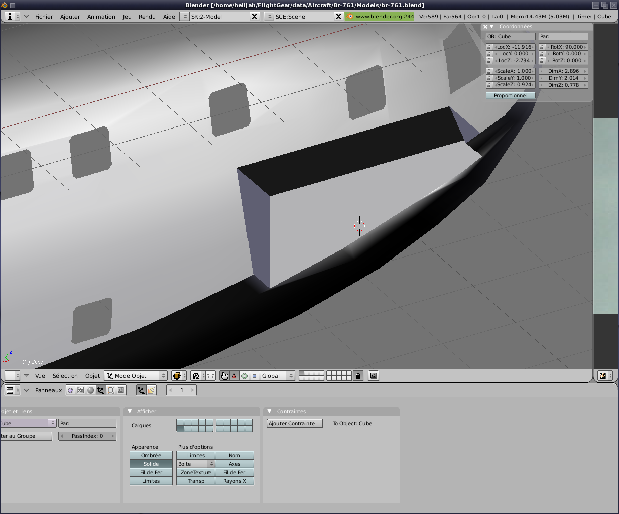
Using a simple box (Image 1) that we have just put
over the fins and a horse on the wing with a few adjustments if
échéants, an operation booléene type "Subtraction" can be a hole in the
wing. Both
sides of departure, the wing box and are sent away in another layer and
used later to form the wing.
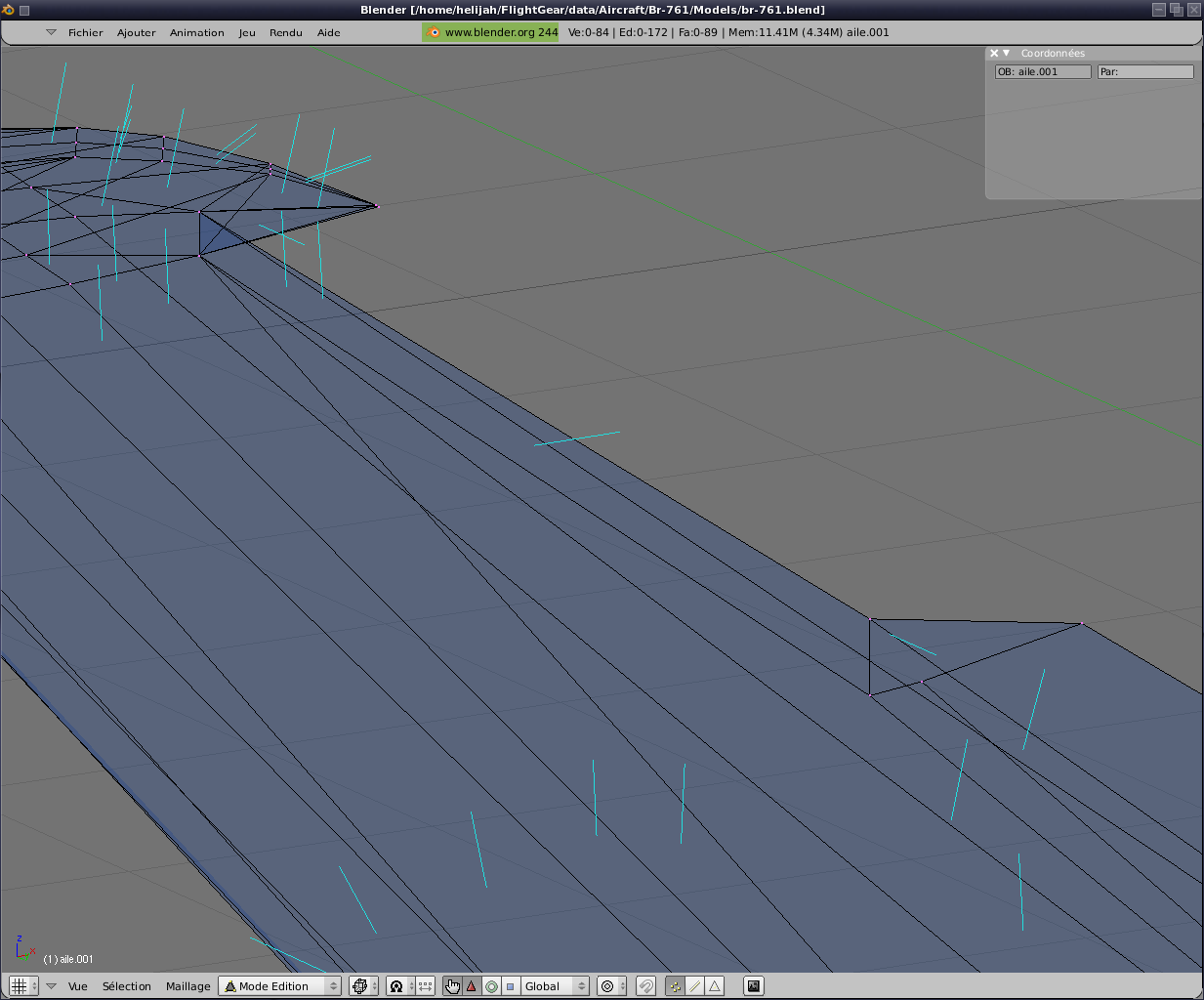
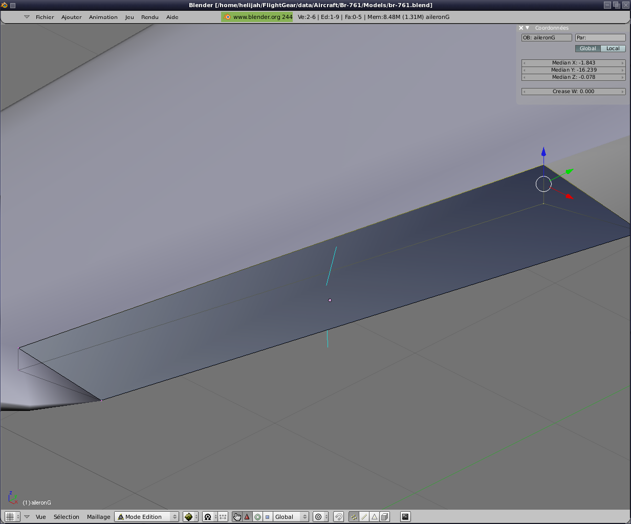
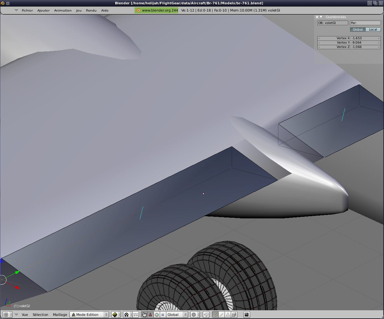
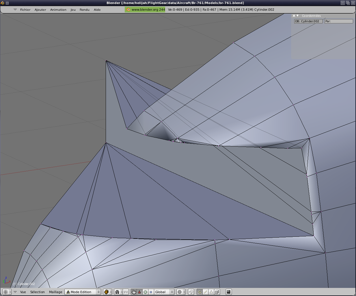
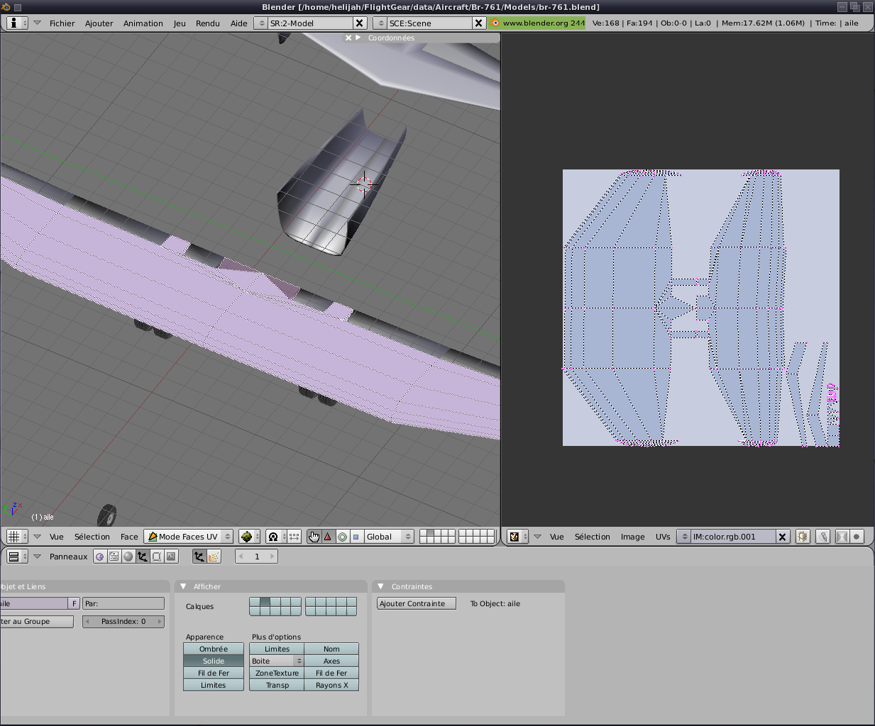
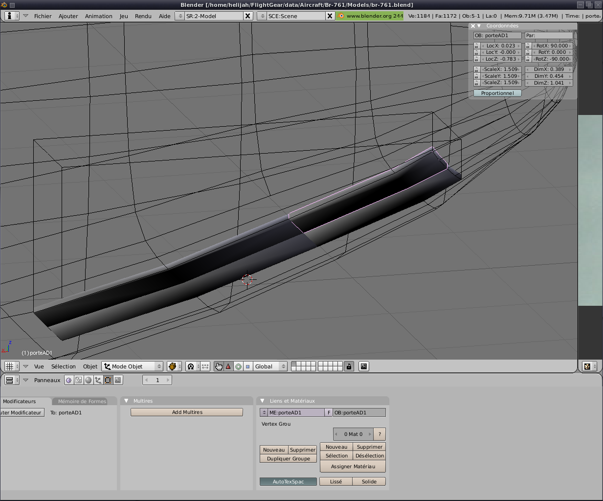
You will notice (image 2) that the
result of a soustration objects in Blender is not always perfect.
Then a few touches. Remove points overpaid and pasting points
to eventually get the desired result (image 3).
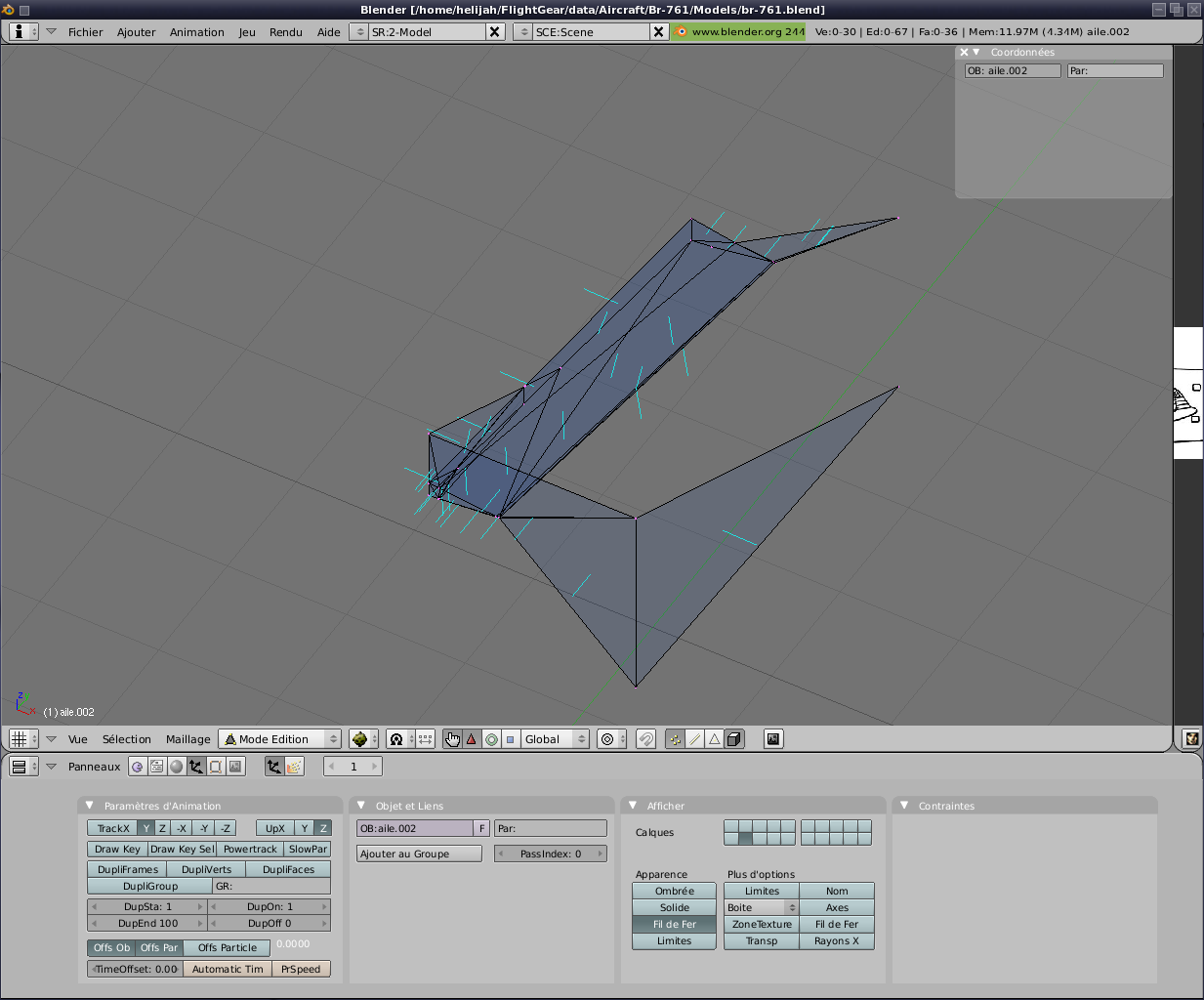
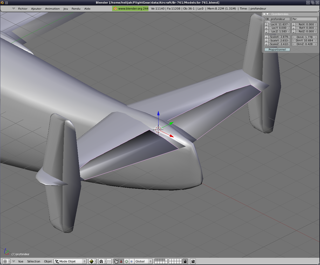
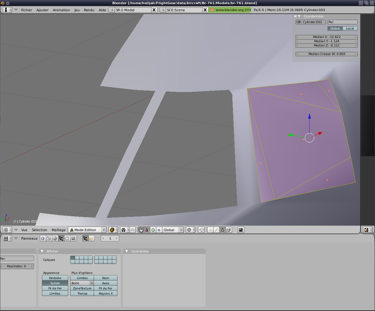
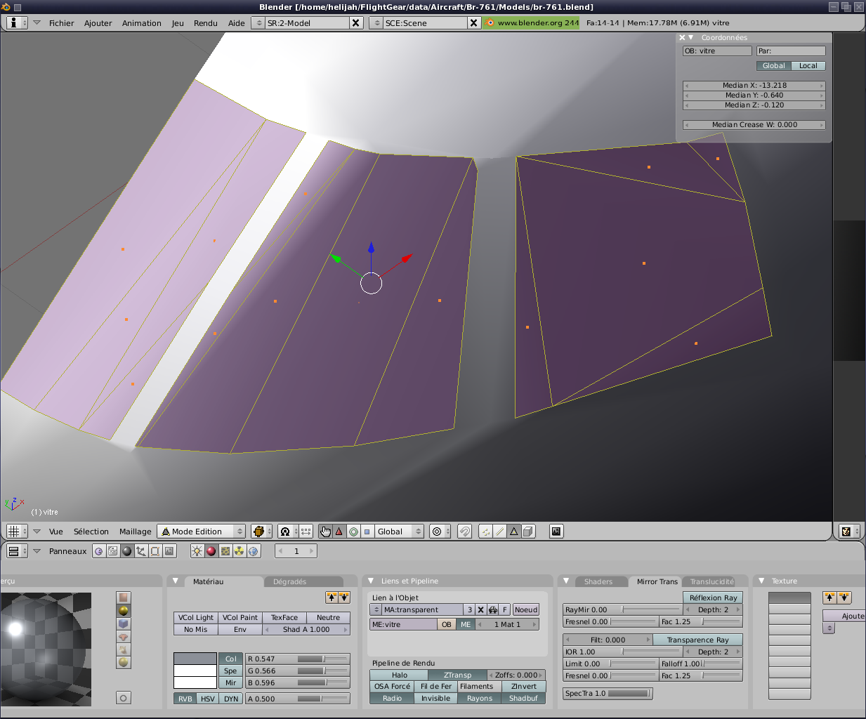
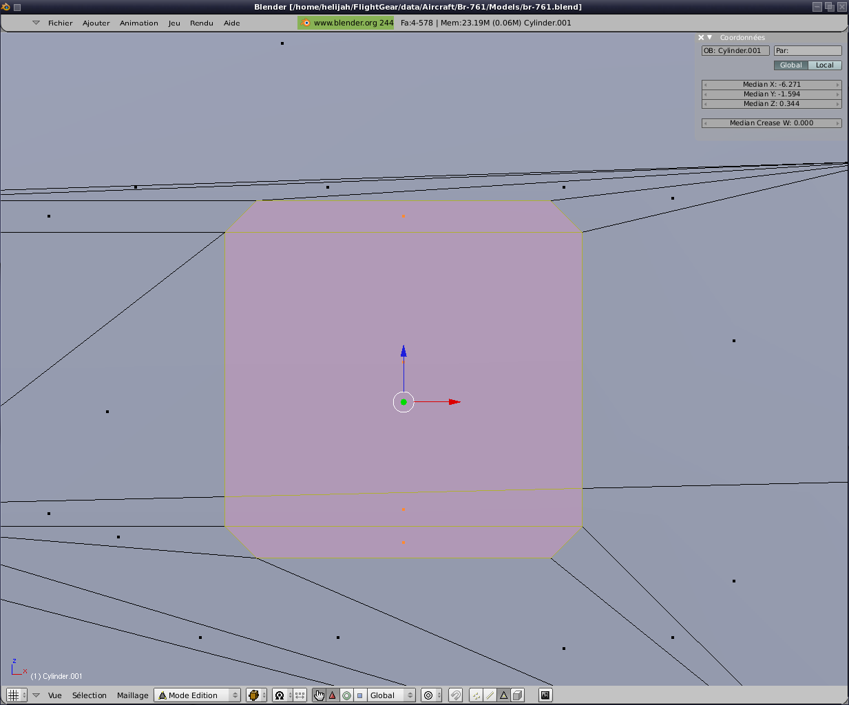
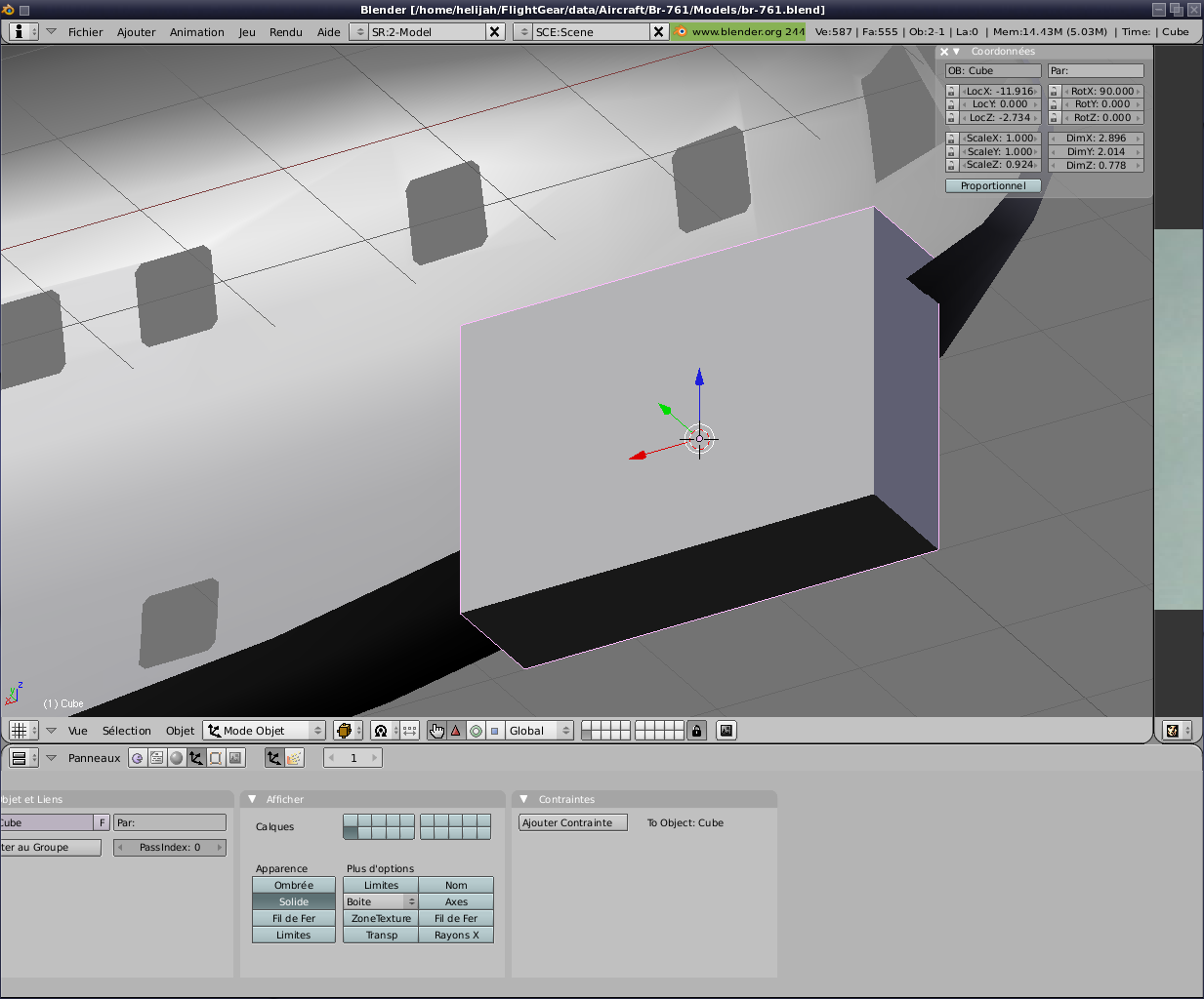
Now the wing itself.
Same principle that
previously but with an operation Booléenne type "Intersection" with
always the same small concerns in Blender and even solutions to achieve
its ends (image 5)
I pass completion shutters, gourvernes direction and depth.
The principle is always the same single positions and shapes change a
little.
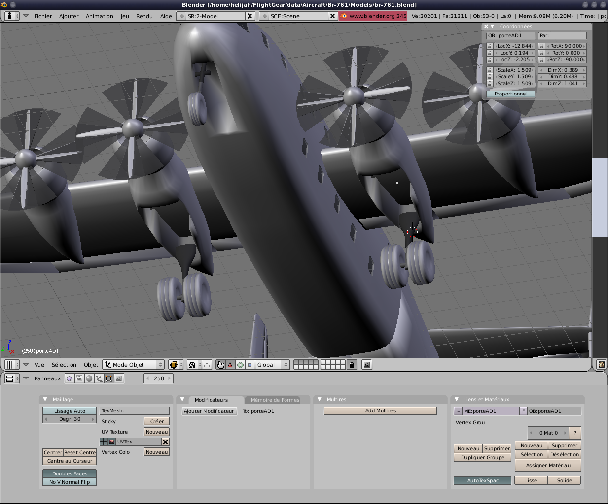
Finally, before attacking animations, we will add propellers (and disks
that simulate high-speed rotations). Personally, I get a propeller already done for my Noratlas 2502.
In fact two propellers, one with no right and no one with a left.
We copy and we place.
Although we have noted the various centres of rotation, translation
etc. .. of different moving parts.
Come on, let's go. A chance for us the coordinates and
values given by Blender
correspond to the same values in FlightGear
expressed in metres. Exactly what we needed.
For
rotation, most of the time, a point and an axis enough. Nevertheless, when the axis is not along one of the three axes of
reference (X, Y or Z) calculations can be more complicated.
Two solutions to this :
1 - The use of the excellent script for export Blender Melchior FRANZ that
you find in the sources of FlightGear
(utils / Modeller /
fgfs_animation.py), which is to be placed in the file
"scripts" of your Blender.
2 - Set two points along the axis and
leave FlightGear
do the rest;)
Note: The second
solution is not working for translations to date.
So
in this case the first solution is the only available (in addition to
the calculations by hand of course).
We are therefore:
|
bolG |
bolG |
aileronG |
voletG |
voletG |
depth |
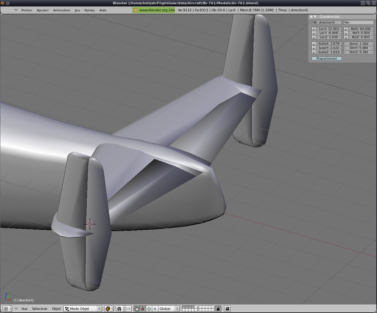
directionG |
roueA |
roueG |
| x |
-7,945 |
-8,979 |
-1,843 |
-1,950 |
-1,653 |
-1,836 |
-1,653 |
-1,653 |
11,637 |
12,013 |
-13,758 |
-2,603 |
| y |
-8,032 |
-3,911 |
-16,239 |
-19,880 |
-9,064 |
-16,233 |
-1,820 |
-9,064 |
0,000 |
-6,048 |
0,000 |
-3,956 |
| z |
-1,023 |
-1,144 |
-0,078 |
0,344 |
-1,066 |
-0,191 |
-1,146 |
-1,066 |
1,585 |
1,793 |
-4,151 |
-3,954 |
For objects inspired by
the left and centre. For objects of the right, just take those left
and reverse the value Y.
The center will also bowls for the propellers and their associated
discs.
We can
now add or modify the XML file the dossier "Models" for
example wing left the following code:
<animation>
<type>rotate</type>
<object-name>aileronG</object-name>
<property>surface-positions/left-aileron-pos-norm</property>
<factor>15.0</factor>
<axis>
<x1-m> -1.843 </x1-m>
<y1-m> -16.239 </y1-m>
<z1-m> -0.078 </z1-m>
<x2-m> -1.950 </x2-m>
<y2-m> -19.880 </y2-m>
<z2-m> 0.344 </z2-m>
</axis>
</animation>
Remarks: I have
numbered engines from left to right from 0 to 3.
With therefore left outside No.
0, the left inside No. 1, right inside the No. 2 and the right outside
No. 3.
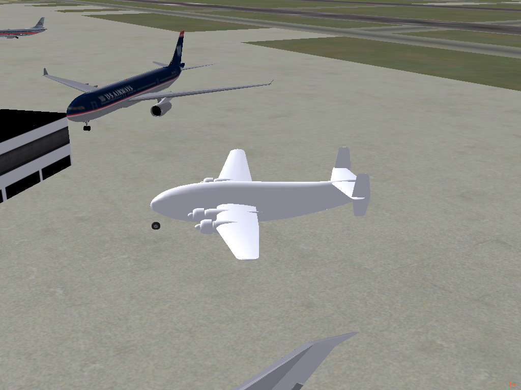
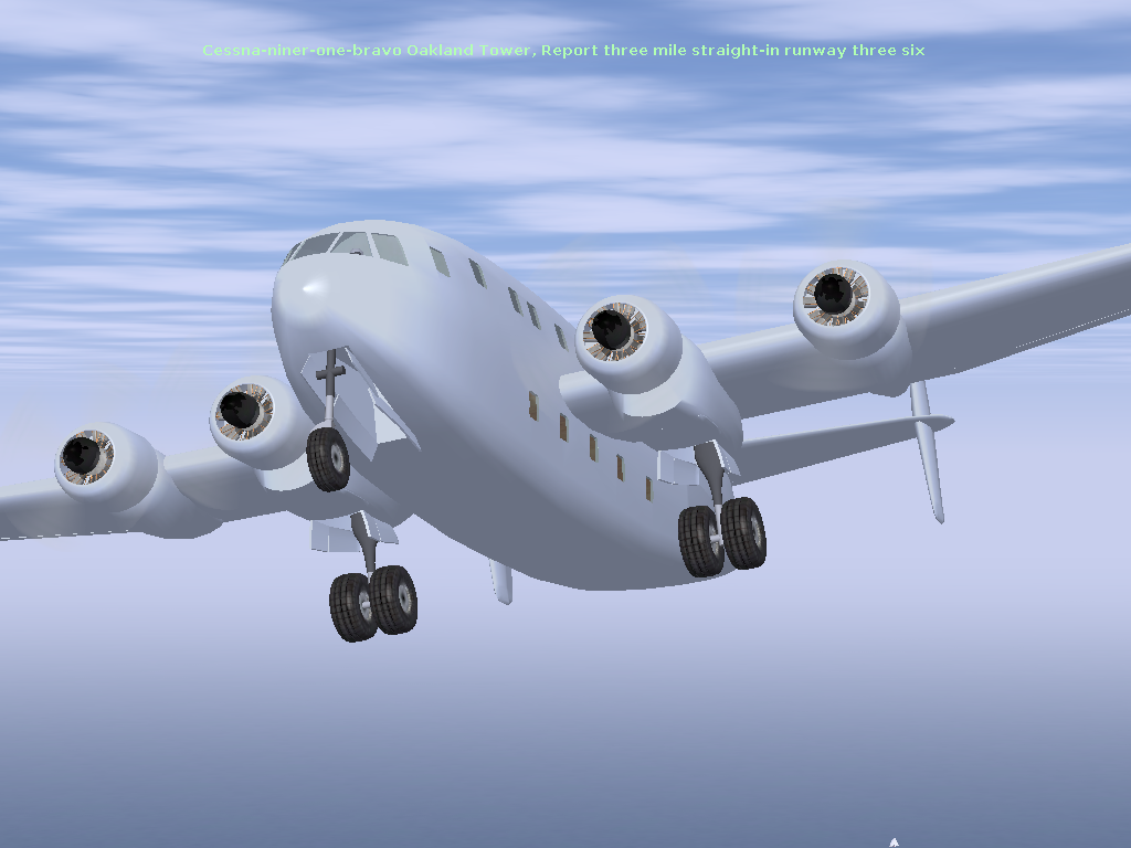
Let's see the result in FlightGear:

Well, tracks emerging, the ailerons move in the
right direction, the propellers turning ... Everything is fine. We can continue ;)
And now it is
time to move the parties difficult. That is, making holes in the fuselage to the
cockpit, the windows and doors.
The principle is always the same, simple
objects (usually created from boxes or cylinders) and function
Booléenne "Embezzlement" will do wonders. With the course still needed a few touches here and there.
"A drawing is better
than a long speech" they say. So I leave you to look:
Although we are therefore with a cockpit (for the éxtérieur) and
portholes. But
the "deux ponts" is primarily an aircraft with ......... two bridges.
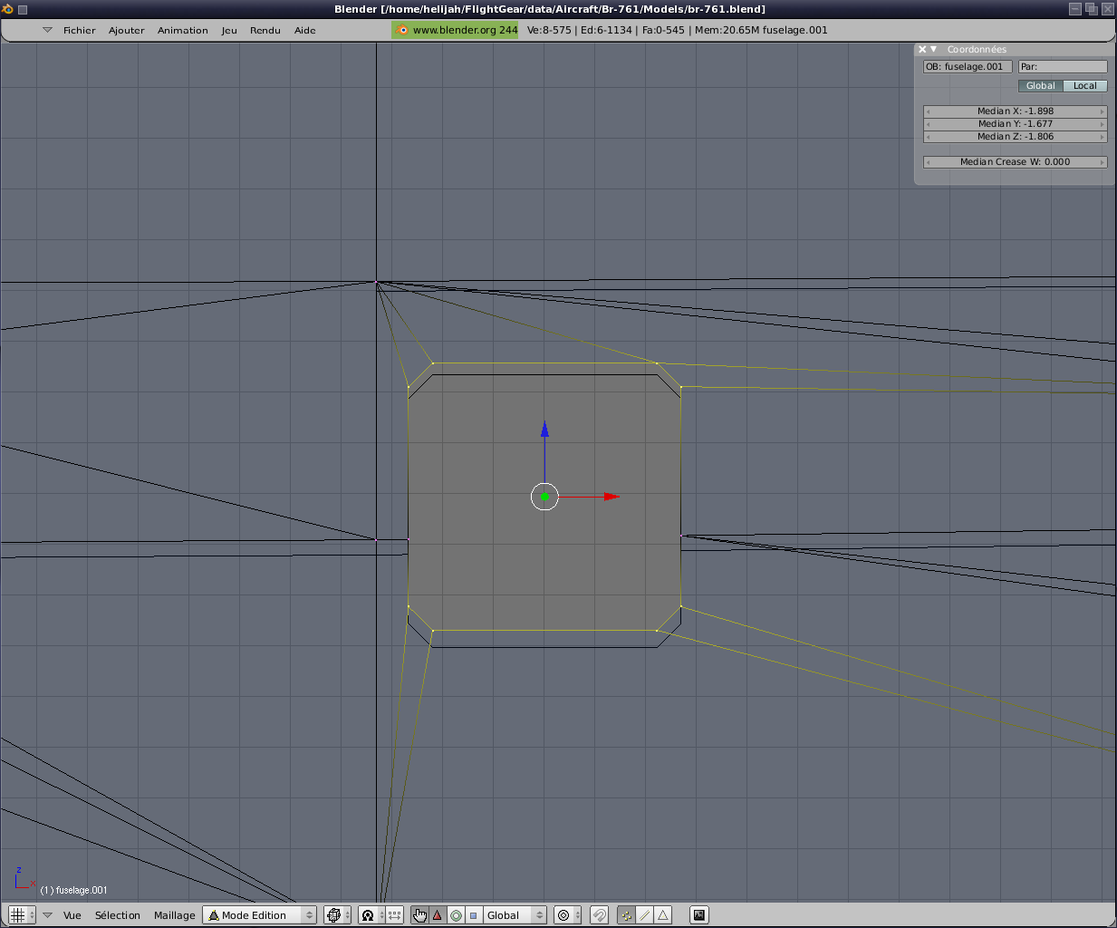
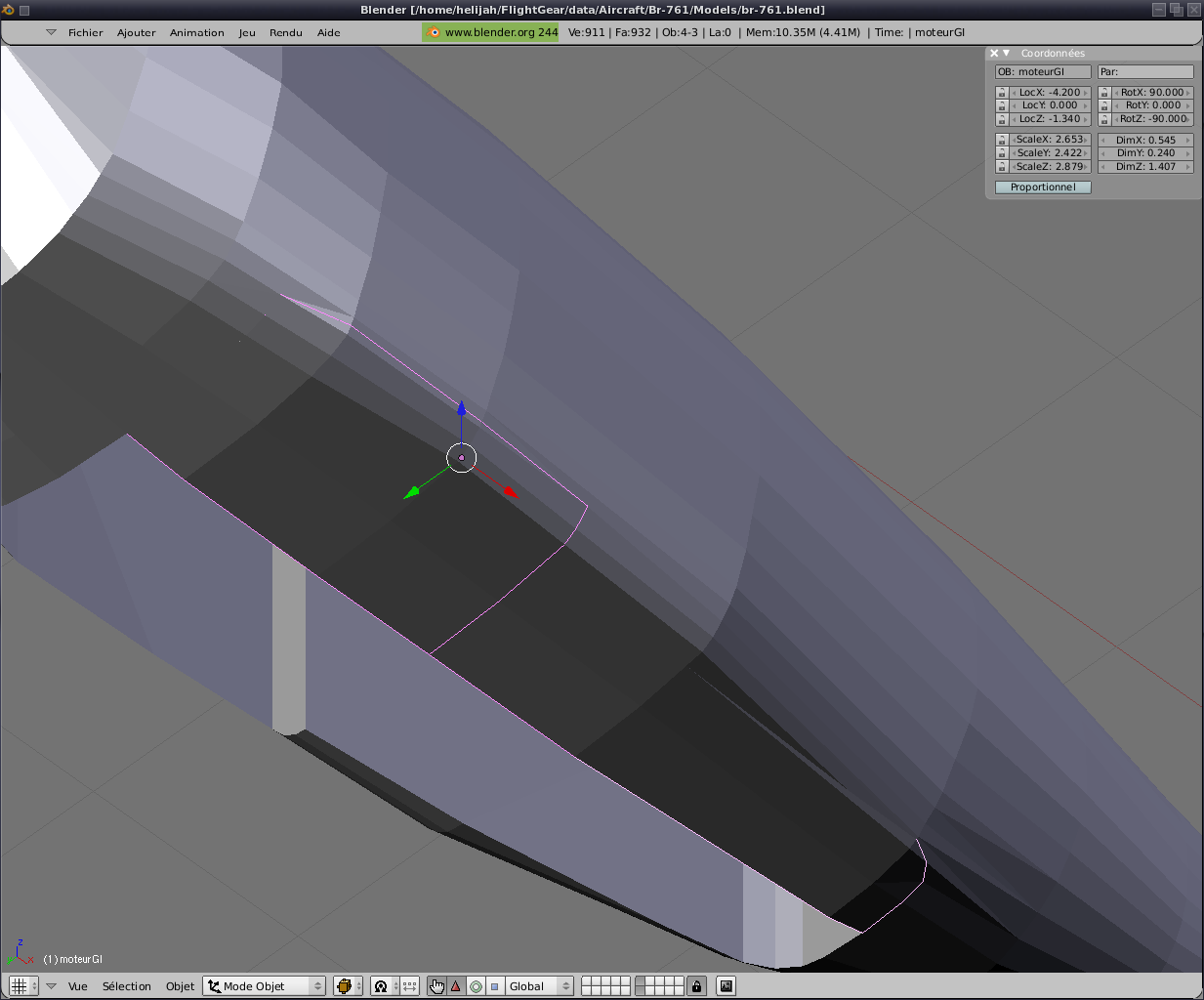
We will now create the cargo doors at the rear of the fuselage.
Now you know the methodology;) A simple object
that is removed from the fuselage. Some corrections because the Booleans are not always perfect and doors
creation by the merger Booléenne intersection. Here are some images that
relate all this:
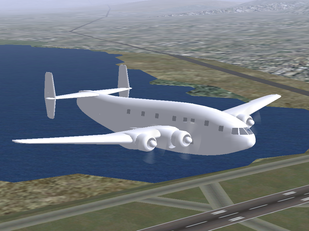
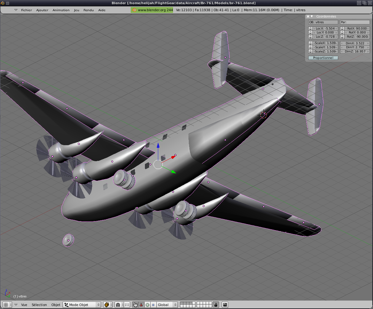
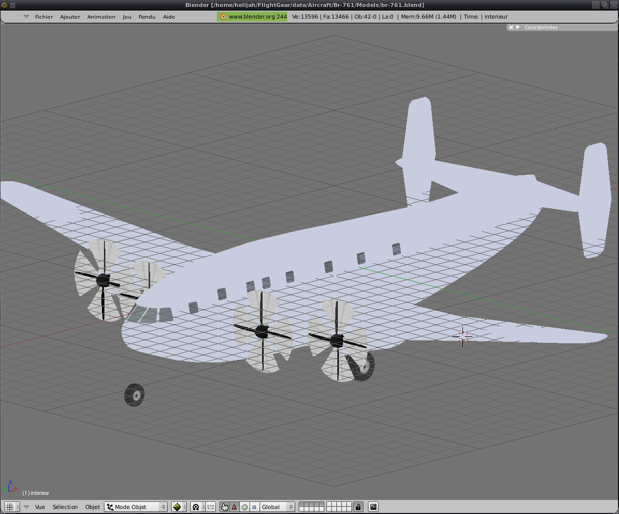
We are at a time that some
expect. We have a fuselage, wings, propellers, rudder, wheels, a temporary FDM
in which I added 2 engines and moved the wheels. In short, he flies. You want us to try it? Did you have fun and
take u shortly before thereafter.

Click here to retrieve the
first tar.gz of the tutorial;)
Well, I hope ête you great fun ;)
Now if we give a little thickness to the fuselage.
Indeed, so far, it exists only in its outer part.
We are going to duplicate the
fuselage ( "Shift d") and then separate copy of the original (key "p").
Finally, playing on the views, we will slightly reduced its size.
For this to be quite realistic we must come
together inside and outside. And for this to happen so I own a
fairly simple method which gives very good result.
First, we must
ajouster points portholes, as those of the interior are no longer
facing those outside. This is due to change in
overall size.
Then we select (in line) lines around
all windows and the bay. We then copy separate from the fuselage ( "Shift d" then "p").
Finally we stick all
its lines to the object interior previously created (Ctrl J after
selection of two elements). Finally, and
this is the longest we recréons all facets missing (selection of 4
points, then pressing "f"). Ah especially not forgotten to reverse the
direction of nomales for everything inside (the last two photos in the
series above) because this part is seen from inside the plane and not
from outside (or just through the glass;))
Well,
before going further, give a texture to all this history to have a made
a little more interesting in FlightGear. We will not get very far at the
moment. A texture united for whatever is extétrieur and another for the
interior.
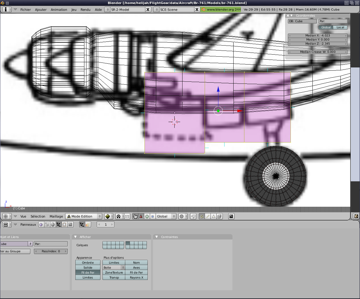
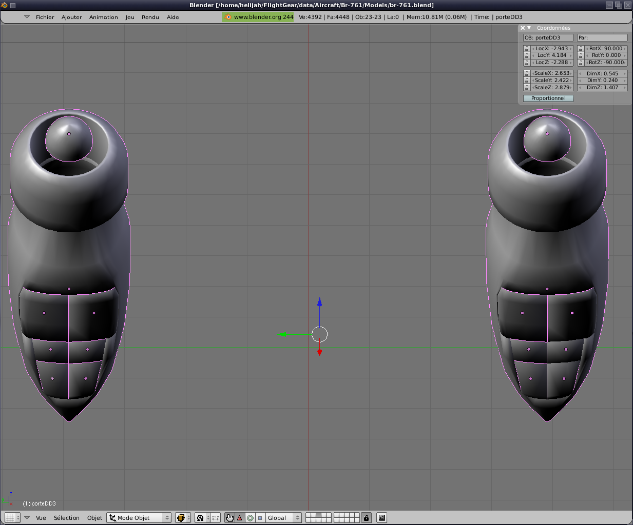
Now we are going to create housing and doors for the front wheel.
Also on the same principle. A simple object, the function
Booléenne subtraction, a few adjustments, resumption of previous
elements but with an operation Booléenne intersection etc. ...
Do not forget to do the same thing with the inner part;). This requires a re-calculation of position textures not forget.
Then it gives cover
for the main wheels. Finally only once. The second is
directed by symmetry of the first ;)
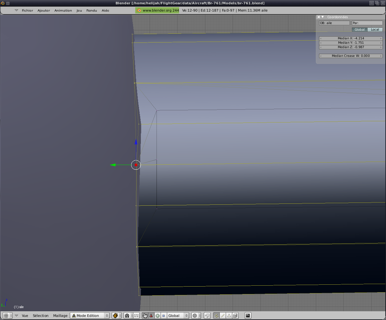
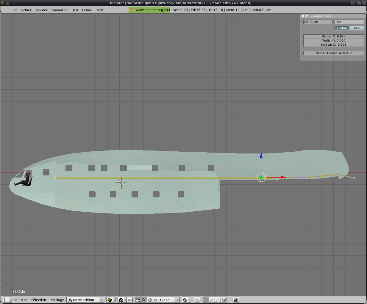
Now let us see inside. First the wings.For the moment
they crossed the fuselage completely. We'll address it easily.
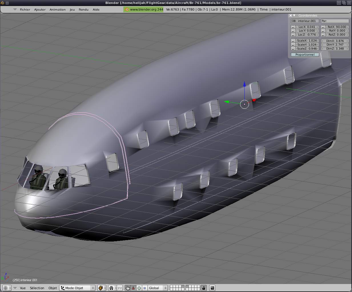
The fuselage now with a
thickness just put the points of connection between the fuselage and
the interior.
Can
history to advance a little we put pilot and co pilot.
This will
allow us to obtain details of sight 0. The driver precisely.
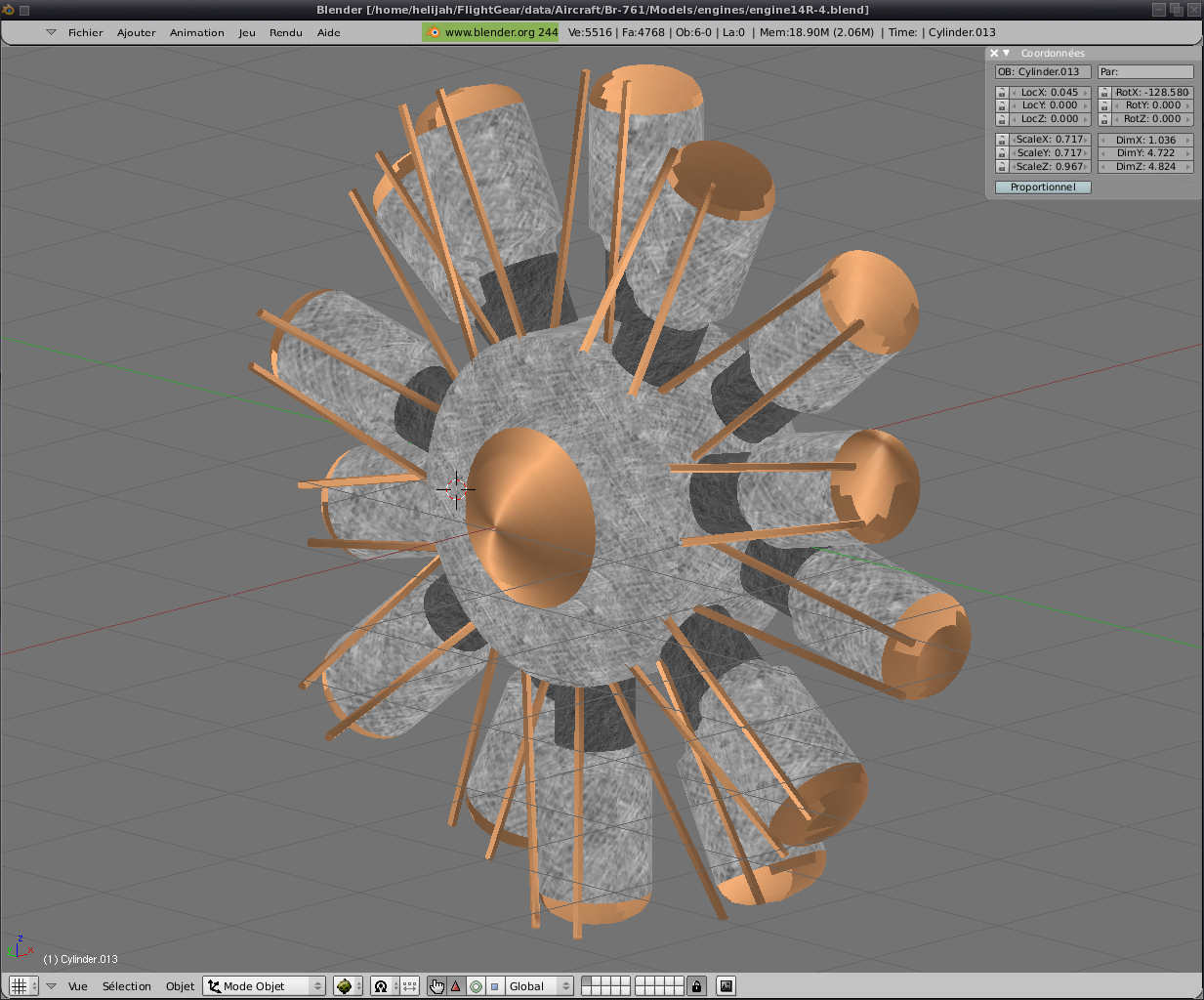
Even before continuing inside, we will hold engines. And yes, you've noticed, the engine fairings are empty. Behind the
propellers a great emptiness we expect ;)
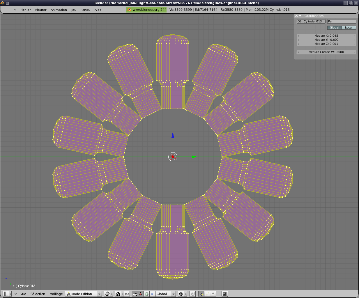
So some research history of me
sleeping beast is less evening and I discover that all the engines
stars to 14 cylinders are made of 2 stars 7 coupled cylinders.
See for example:

source: http://www.agelessengines.com/14cylpic.htm
So that we will made
an engine apart and then we will add 4 times to the aircraft from the
intermediate file xml.
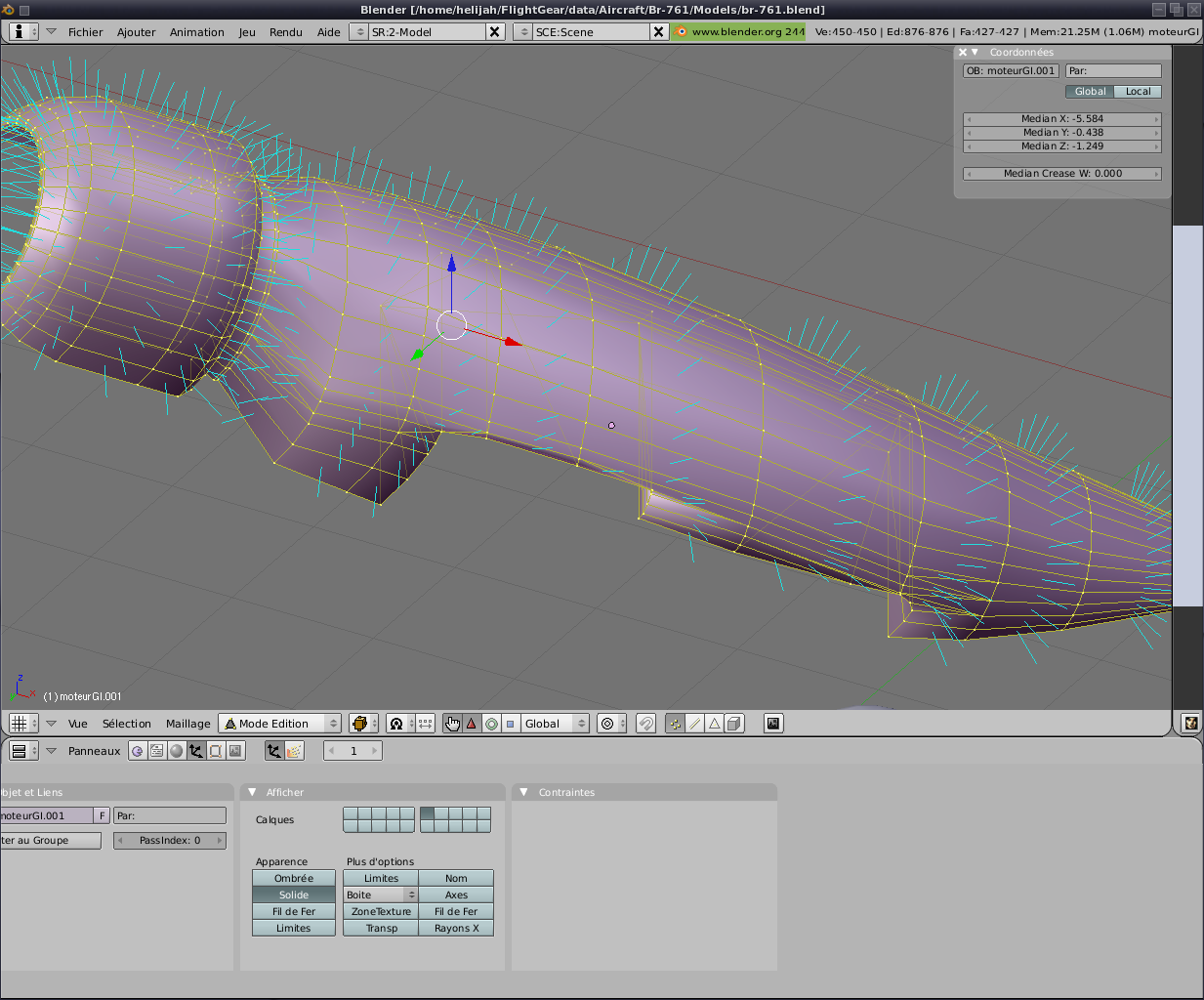
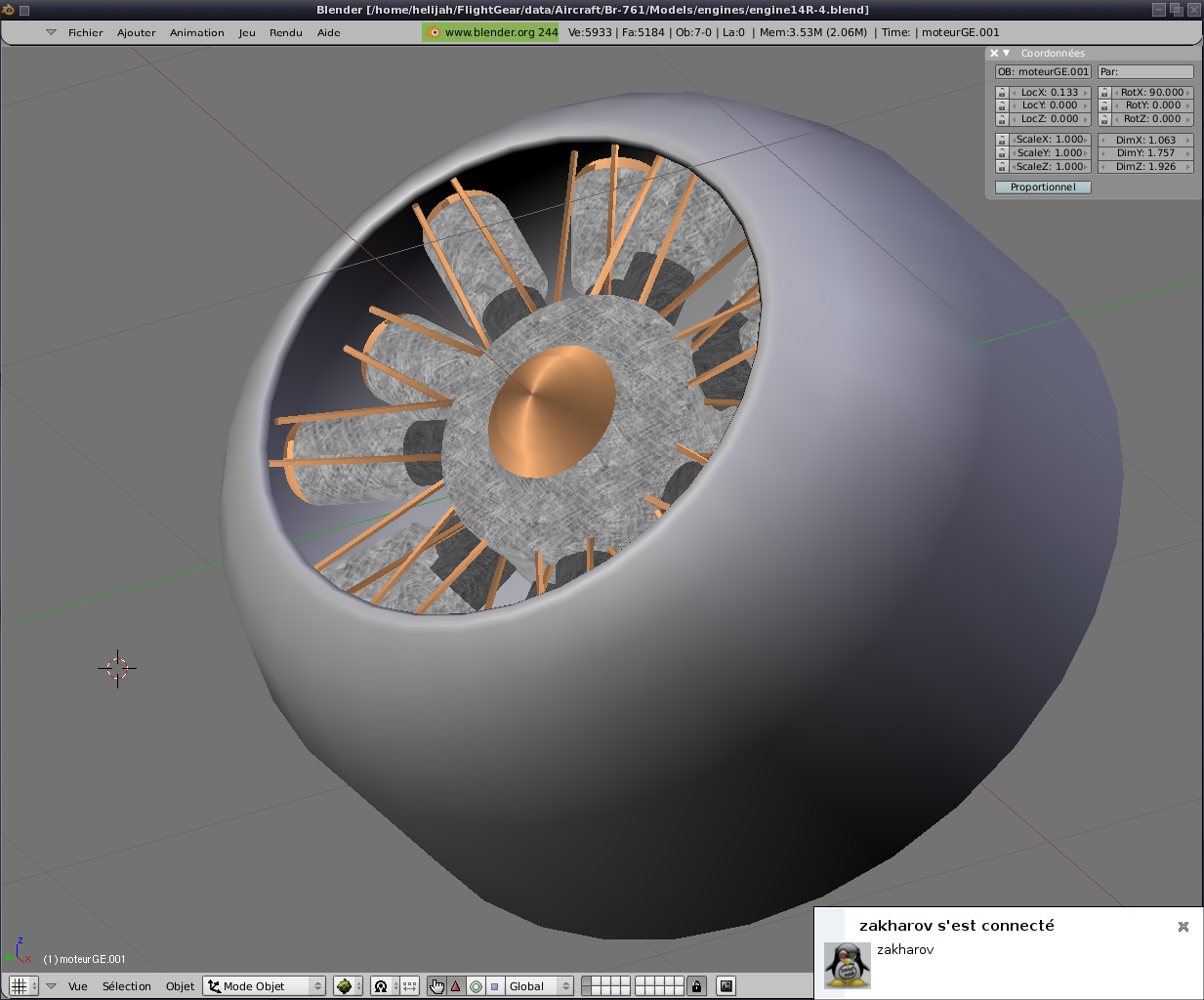
First, the engine:
We do not really detail the
equipment, anyway, because it is practically hidden by the carrénage.
Similarly textures are very quickly selected history
of power tested fairly quickly. It will always be time later to add details if the desire arises.
Finally, you cut a
piece of engine and is used to bring the whole engine throughout our
aircraft. the engine it
centered in the benchmark Blender we will have to recover the positions
they take on the plane.
Nous obtenons :
We get:
|
left outside |
left inboard |
inboard right |
outside right |
| x |
-7,128 |
-8,200 |
-8,200 |
-7,128 |
| y |
-8,032 |
-3,911 |
3,911 |
8,032 |
| z |
-1,023 |
-1,144 |
-1,144 |
-1,023 |
What gives, for example, outboard engine
left in the file / Models/br761.xml
<!-- Extérieur gauche -->
<model>
<path>Aircraft/Br-761/Models/Engines/engine.xml</path>
<offsets>
<x-m> -7.128 </x-m>
<y-m> -8.032 </y-m>
<z-m> -1.023 </z-m>
</offsets>
</model>
Did the gift of the day, the state version of which is already done ;)

Click here to retrieve the
second tar.gz of the tutorial;)
Then a "dexu ponts" to a particularity, it a. ... hum ..... two
bridges. And for the moment, if we open
the rear door we see only the pilots who fly in their seats. Not very realistic is not it?
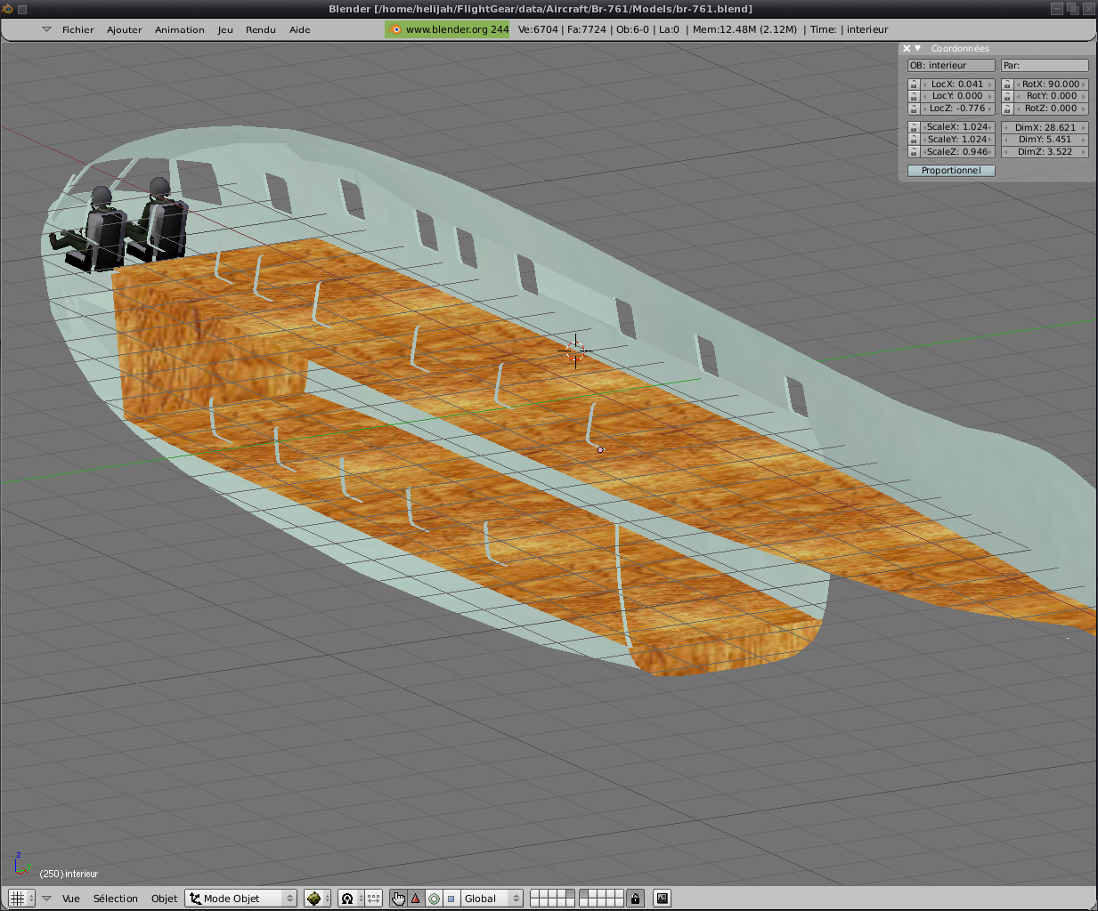
Well, always on the same principle.
A simple object to
instersection with the interior. The result in Blender is quite
uncertain. After a few
touching the planchet becomes cleaner. We do lègerement exceed the object "inside" to avoid problems join (it
will be hidden by the object "fuselage" thereafter). Same principle
always for the planchet of the lower deck and always the same thing to
the ground and the rear of the cabin.
A random texture (I
took wood) for planchets history to see something and the Popular
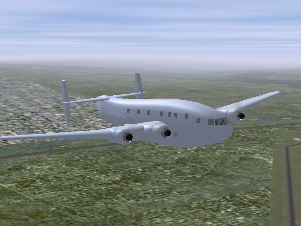
galère ... Finally no! Fly the plane instead.
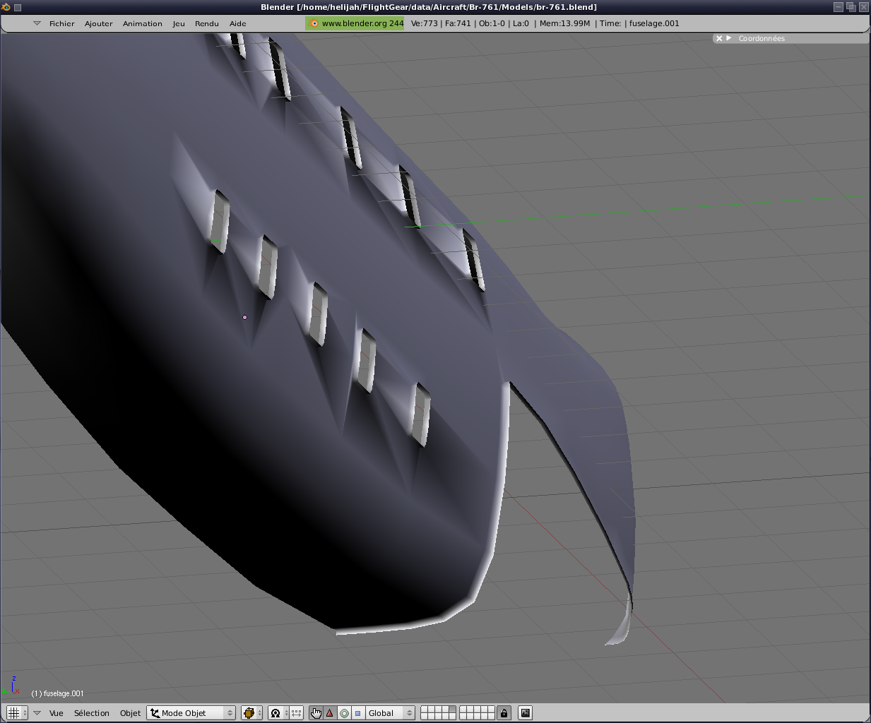
It starts to
take shape slowly but surely not?
A small error in the previous tar.gz sent a
message full of the console at launch. So to make me
forgive, here is a corrected. And with planchet they
are made ;)
Well, to point you aurrez noticed that the wheels are a little held as
if by magic. It is therefore time to actually hang the
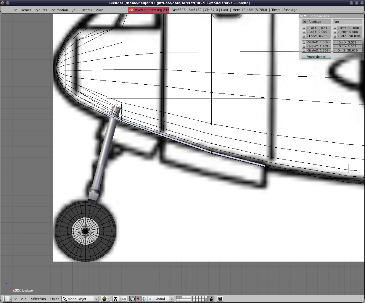
fuselage history if they are a bit more realistic. Let us begin by the nose.
As often we start from a
very simple form. In this case, a cylinder. This time, contrary to the fuselage I quoted him assigns 16 instead of
32. The object is
smaller and is not visible all the time. Both win a few in number of
facets. Some strains in office pictures found on the web. The paste which want the wheel is achieved, as
the wings, with a plan put into forms and then extrude. We think to make the train into two parts
minimum to manage the effects of suspensions.
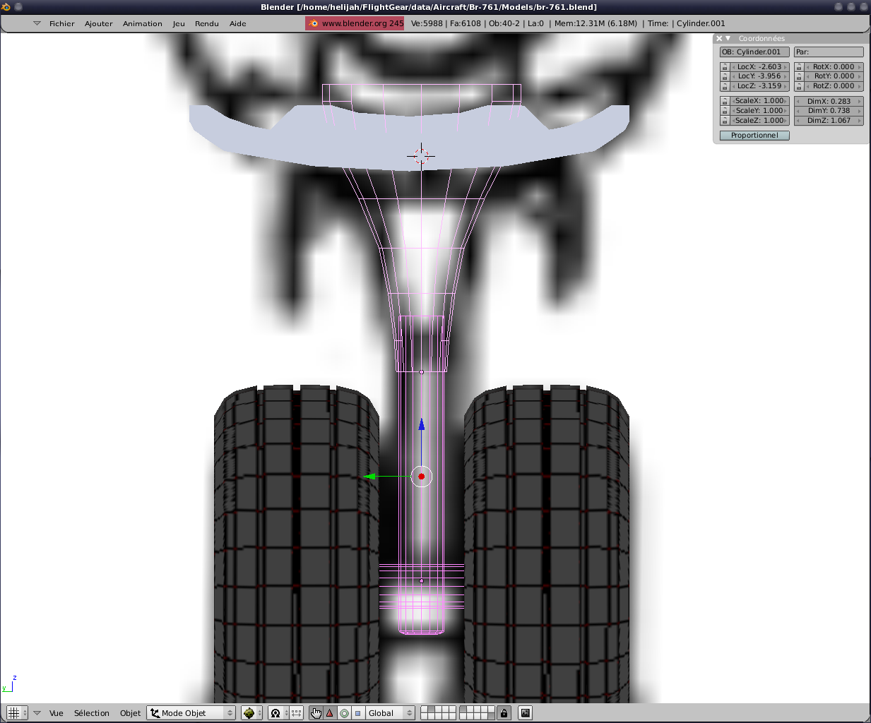
We put together properly and
check that, once returned train more than somewhere. As the vertical axis of all is not quite
along the Z axis, to manage the suspension we will have to calculate
the axis of translation. And no, we find the
superb work of Melchior and export via Blender we can have an axe
without effort.
Now the trains back. The same principles, same systems, in short, we start again only the
general shape change.
Deliberately, I did not detail too trains for not getting lost in
details. But be aware that it is
better to spend some more time on them and add different parts annimées.
The actuators, joints and so on ....
Finally the plane here in the state: Click here
The same with the files included Blender: Click here
Huuu, there is a good time that I did not
come write a few lines in this tutorial me. Well go, we will try
to provide a model that Breguet flight a little more credible than it
currently has.
To do this, we will use YASim.
Yes? A question? You there at the bottom of
the radiator ready .......
- "Why YASim
sir?"
- "Ah! And why not!"
So this question
is resolved to proceed thereafter.
Important:
Above
all, be aware that even if the final, the plane flies, I absolutely do
not control all the ins and outs of YASim. So I will
give you my method of work. Certainly not
the ideal and certainly full of nonsense. But I did not
better for you right now. Those who
know do not hesitate to intervene to explain what is wrong.
So, what is needed. First, some
data size and position. Fuselage, wings, control
surfaces, wheels, etc. ...
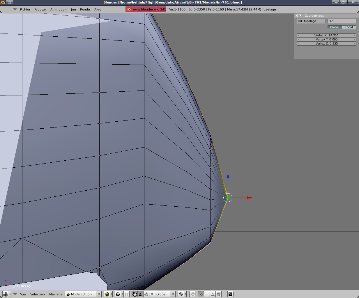
Let the fuselage. Below you can see
the most forward: x =- 14,305 y = 0.0 z
=- 1,154
the most backward: x 14,351 = y = 0.0 z = 0,255
and the width of the fuselage: with
= 3,579
We remember that in YASim the X and Y coordinates are
reversed on their axis.
The reported language YASim we give:
<!-- Fuselage -->
<fuselage ax="14.305" ay="0" az="-1.154"
bx="-14.351" by="0" bz="0.255"
width="3.379" taper="0.9" midpoint="0.7"/>
taper is the ratio
between the smallest width and greater. In this case the value 0.9 is purely objective and absolutely not the
result of a calculation :(
midpoint If I have
understood is, in percentage terms, the portion of the fuselage or the
width begins to change. Ditto for this time. Value purely objective.
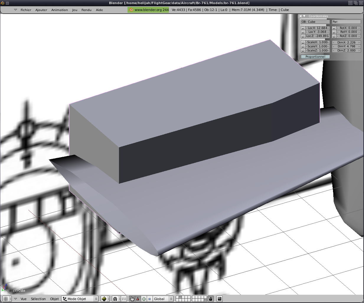
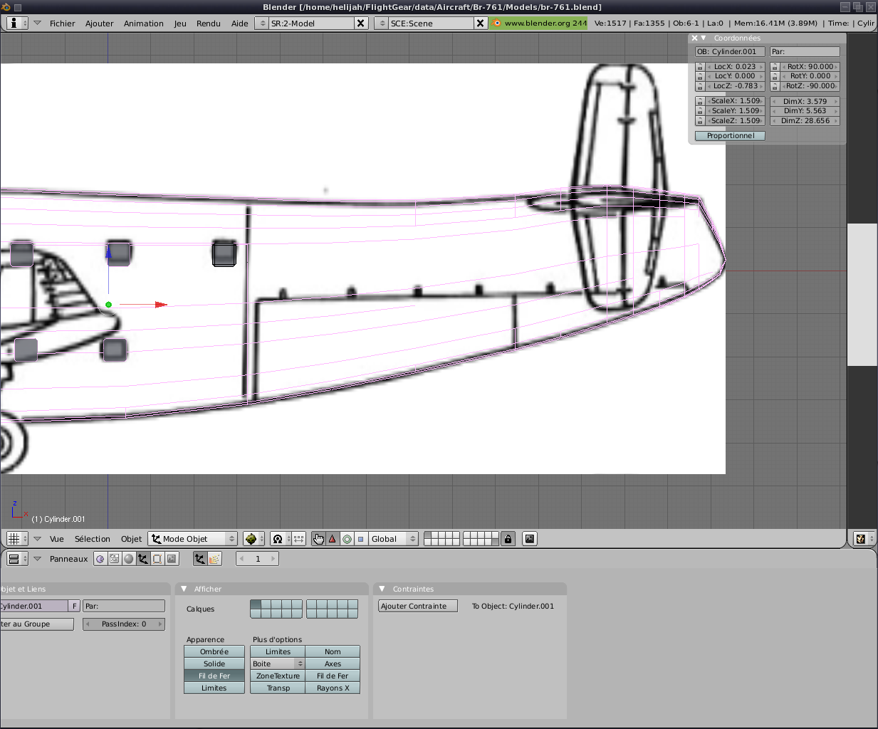
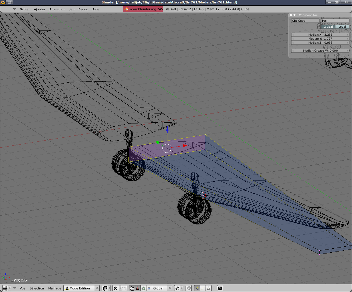
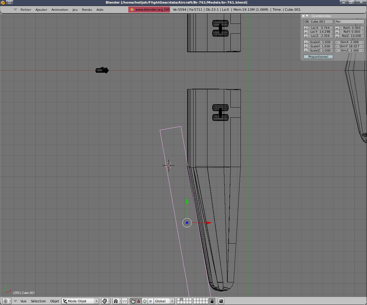
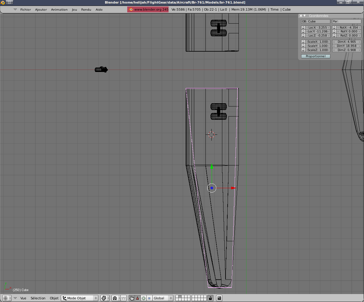
At the turn of the wings now. In YASim only the left
wing is necessary. The line is
automatically generated by symmetry. To do this, I use a box
that I just put on top of the left wing to retrieve the global values.
The reported language YASim we give:
<!-- Wing -->
<wing x="3.255" y="1.727" z="-0.255"
length="18.958"
chord="4.905"
sweep="2"
dihedral="4.35"
taper="0.258"
camber="0.4"
incidence="0.0"
twist="0.0">
<stall aoa="10" width="6" peak="1.5"/>
<flap0 start="0" end=".6" lift="1.4" drag="1.9"/>
<flap1 start=".6" end=".95" lift="1.4" drag="1.2"/>
<control-input axis="/controls/flight/flaps" control="FLAP0"/>
<control-input axis="/controls/flight/aileron" control="FLAP1" split="true"/>
<control-input axis="/controls/flight/aileron-trim" control="FLAP1" split="true"/>
<control-output control="FLAP0" prop="/surface-positions/flap-pos-norm"/>
<control-output control="FLAP1" side="left" prop="/surface-positions/left-aileron-pos-norm"/>
<control-output control="FLAP1" side="right" prop="/surface-positions/right-aileron-pos-norm"/>
<control-speed control="FLAP0" transition-time="5"/>
</wing>
But pause a moment sour all these values and see a
little more detail all that.